Contact lens and method of manufacturing the same

a technology of contact lens and manufacturing method, which is applied in the field of contact lens, can solve the problems of poor circumferential stability, more difficult to achieve good wear comfort and circumferential stability, and inability to achieve the desired level of wear comfort and circumferential stability, and achieve the effect of high degree of accuracy and desired wear comfort and stability

Active Publication Date: 2010-03-11
MENICON CO LTD
View PDF11 Cites 35 Cited by
  • Summary
  • Abstract
  • Description
  • Claims
  • Application Information

AI Technical Summary

Benefits of technology

[0008]With the foregoing in view, it is accordingly one object of the present invention to provide a novel method of manufacturing a contact lens affording desi

Problems solved by technology

Consequently, it will be more difficult to achieve good wear comfort and circumferential stability with a 180° cylindrical axial angle lens as compared with a 90° cylindrical axial angle lens.
Further, in the case of a lens having a cylindrical axial angle of 45° for example, irregular torque will tend to arise due to the asymmetrical sideways profile, and circumferential stability will tend to be poor.
Depending on the individual, such differences may result in the problem of inability to achieve the desired level of wear comfort and circumferential stability.
Additionally, as progressively greater levels of cylindrical power are established, the difference in curvature ratio between the optical zone and the peripheral zone will become greater as well, so the joint zone will tend to inflect, which tends to result in diminished wear comfort.
However, with contact lenses like that taug

Method used


Image

  • Contact lens and method of manufacturing the same
  • Contact lens and method of manufacturing the same
  • Contact lens and method of manufacturing the same

Examples


Embodiment Construction

[0054]A fuller understanding of the present invention will be provided through the following detailed description of the preferred embodiments of the invention, with reference to the accompanying drawings.

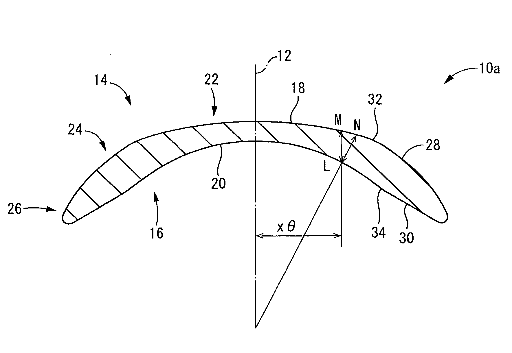
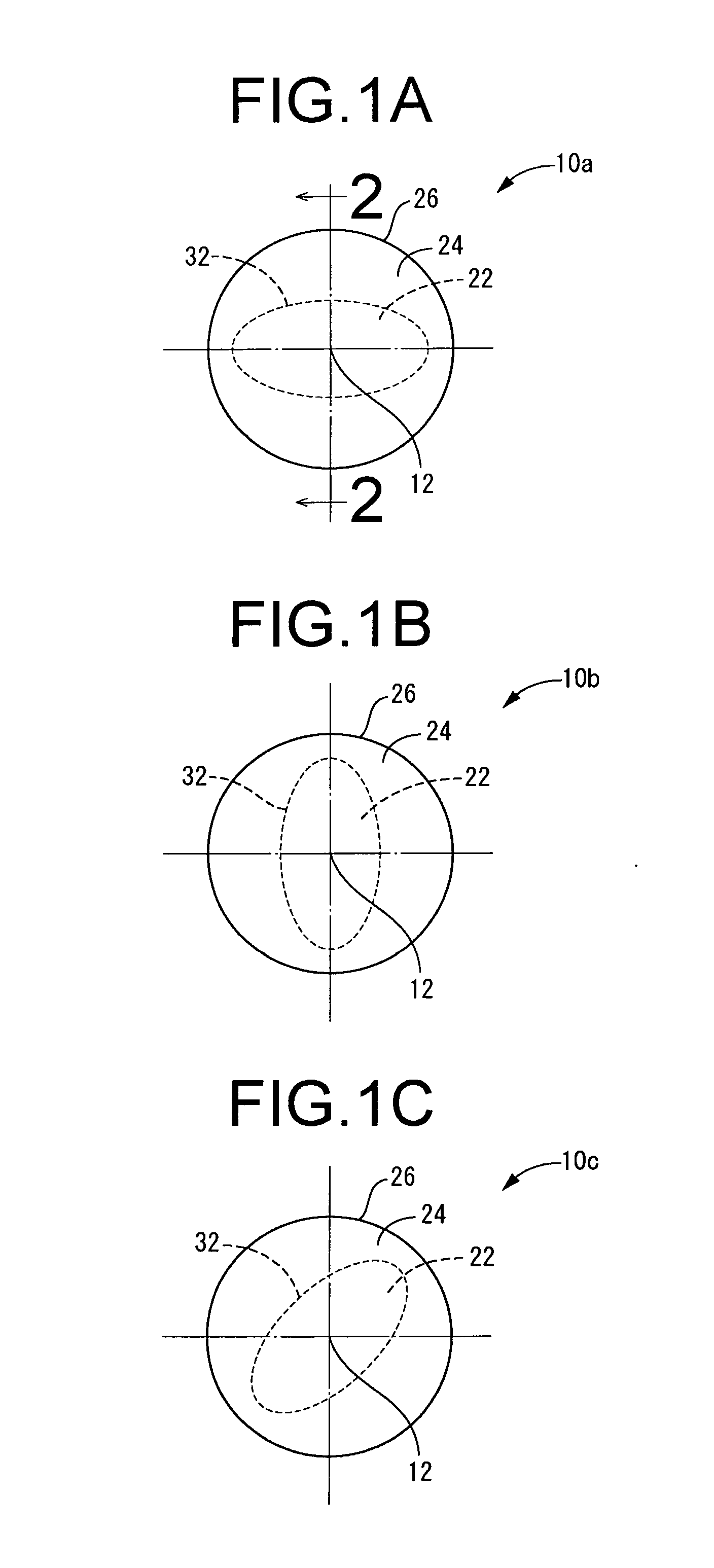
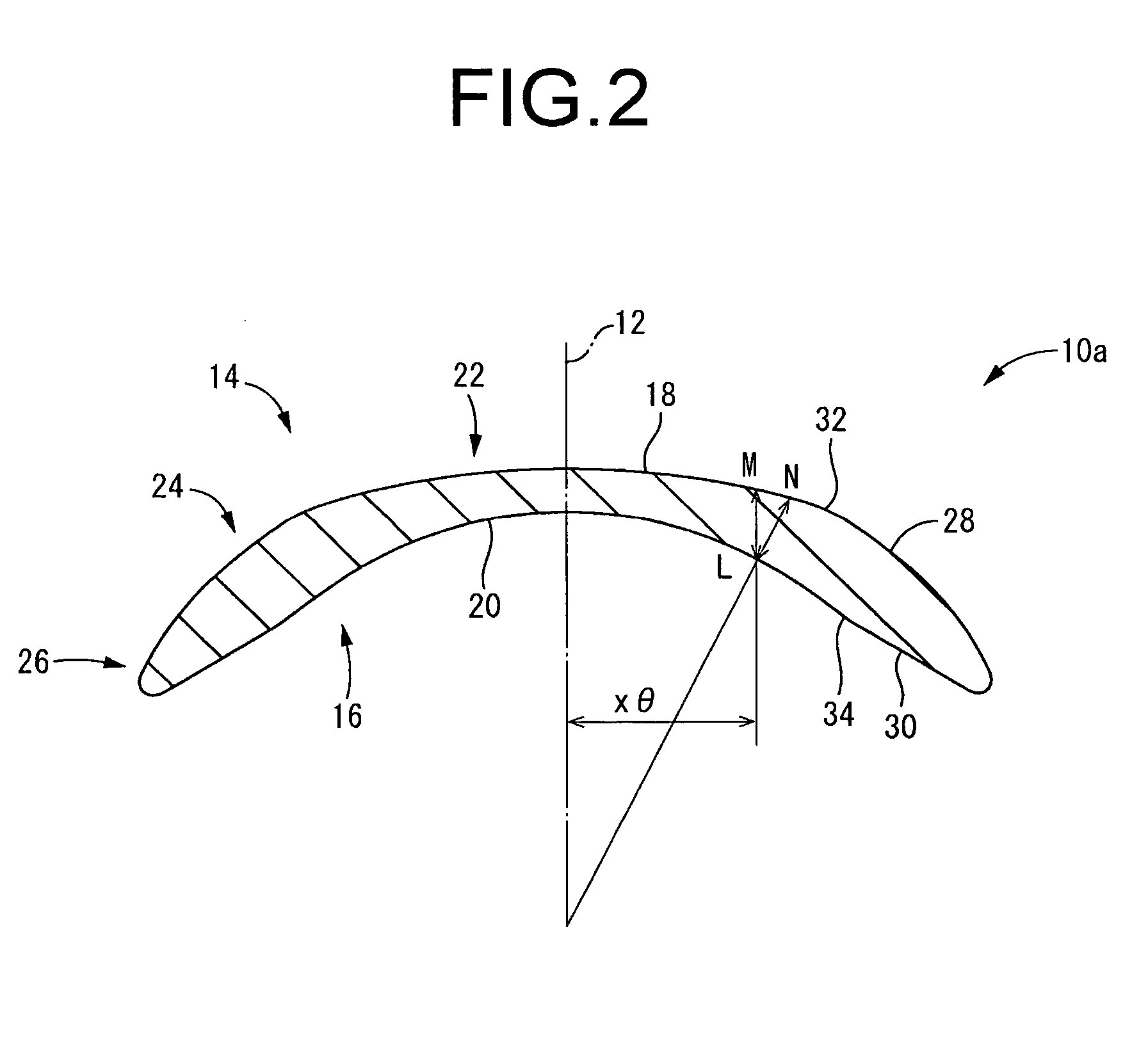
[0055]First, FIGS. 1A, 1B and 1C depict a plurality of contact lenses 10a, 10b, 10c selected appropriately from a contact lens series as a first embodiment of the present invention. The series of contact lenses is composed of a combination of several contact lenses whose optical zones 22 (discussed later) have mutually different optical characteristics, e.g. different cylindrical axial angle settings in the case of the present embodiment. Based on an examination of the optical system of the eye of the wearer, the examiner, e.g. an ophthalmologist, will select from the plurality of contact lenses one appropriate lens having optical characteristics appropriate for the wearer, for provision to the wearer.

[0056]The individual contact lenses 10a, 10b, 10c that are elements making up the...


PUM


Abstract

A novel method for manufacturing a contact lens in which wearing comfort and stability in the circumferential direction that are aimed at can be achieved consistently with a high degree of accuracy irrespective of a profile of an optical zone. An optical zone provided in a center of a lens has a concave rear surface optical zone substantially matching a surface profile of a cornea and has a convex front surface optical zone imparting required spherical diopter power and geometrical center thickness, and a face of either the rear surface optical zone or the front surface optical zone is designed to impart thereto cylindrical power and axial angle required for a toric surface. Furthermore, a junction thickness is established in a joint zone that connects the optical zone with a peripheral zone at multiple sites in a circumferential direction about a geometrical lens center axis of the optical zone. Position of the joint zone is determined on the circumference from profiles established on the rear surface optical zone and the front surface optical zone so as to connect points satisfying the junction thickness thusly established.

Description

TECHNICAL FIELD[0001]The present invention relates to a contact lens of soft or hard type, and in particular relates to a contact lens of novel design affording excellent wear comfort and stability in the circumferential direction irrespective of the profile of the optical zone; and to a method of manufacturing a contact lens.BACKGROUND ART[0002]Contact lenses of soft or hard type (hereinbelow collectively designated as “contact lenses”) are typically furnished in the center part of the lens with an optical zone that affords certain optical characteristics, and a peripheral zone provided about the circumference of the optical zone, for stabilizing lens shape. The optical zone and the peripheral zone are connected by a joint zone.[0003]In the case of toric contact lenses for correcting astigmatism, it will be necessary to prescribe a lens provided not just with the required spherical diopter power, but also with appropriate cylindrical power and cylindrical axial angle depending on t...

Claims


Application Information

Patent Timeline
IPC IPC(8): G02C7/04
CPCB29D11/00038G02C2202/08G02C7/047G02C7/04
Inventor HIBINO, SHINGO
Owner MENICON CO LTD
Why Eureka
Try Eureka