Illuminable emblem

Active Publication Date: 2019-04-04
HELLA KG HUECK & CO
View PDF1 Cites 3 Cited by
  • Summary
  • Abstract
  • Description
  • Claims
  • Application Information

AI Technical Summary

Benefits of technology

[0014]It is also advantageous if the transparent region of the front cover at least regionally has a non-transparent coating on

Problems solved by technology

Here, it has been found that, owing to the areal form of the light conductor and owing to the light being laterally coupled out of the light conductor towa

Method used


Image

  • Illuminable emblem
  • Illuminable emblem
  • Illuminable emblem

Examples


Embodiment Construction

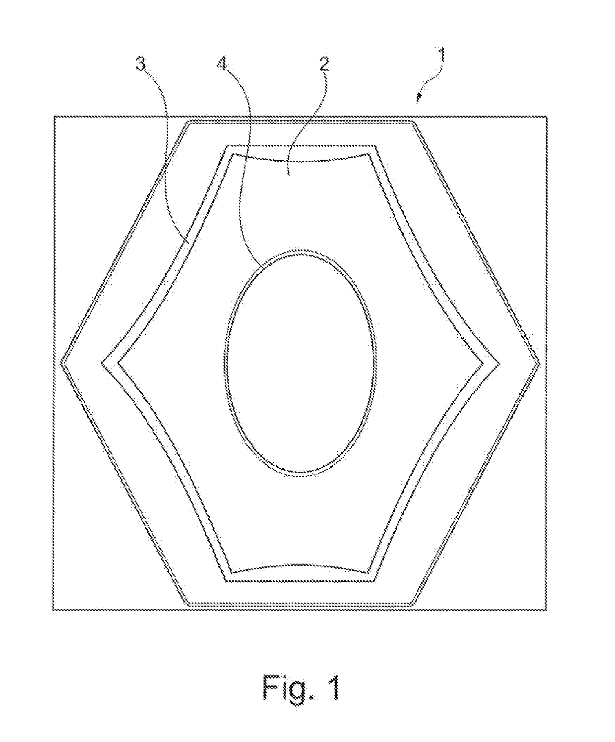
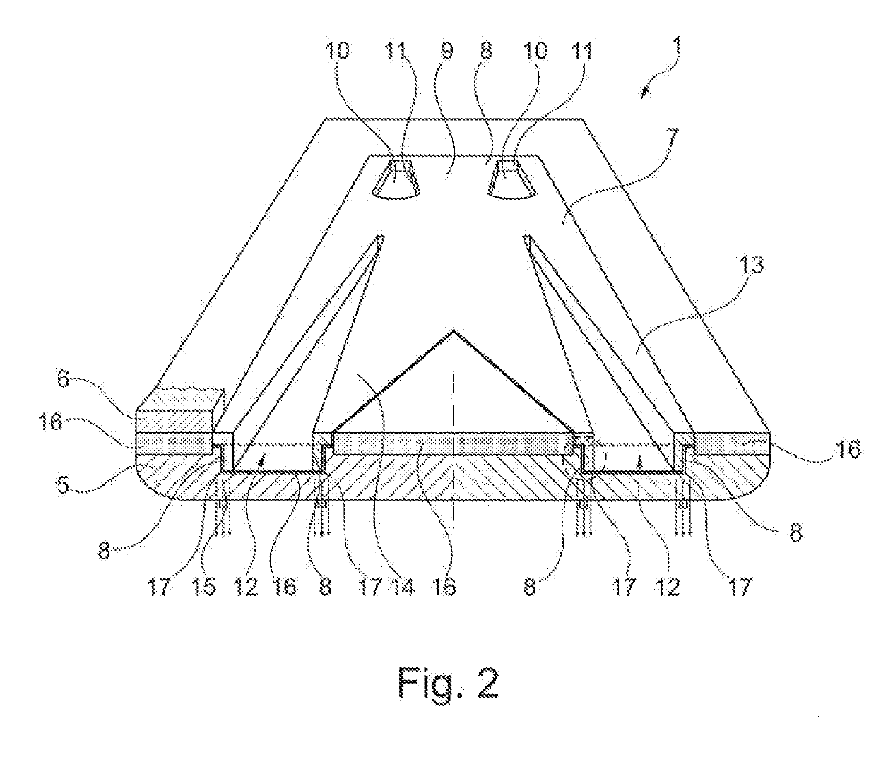
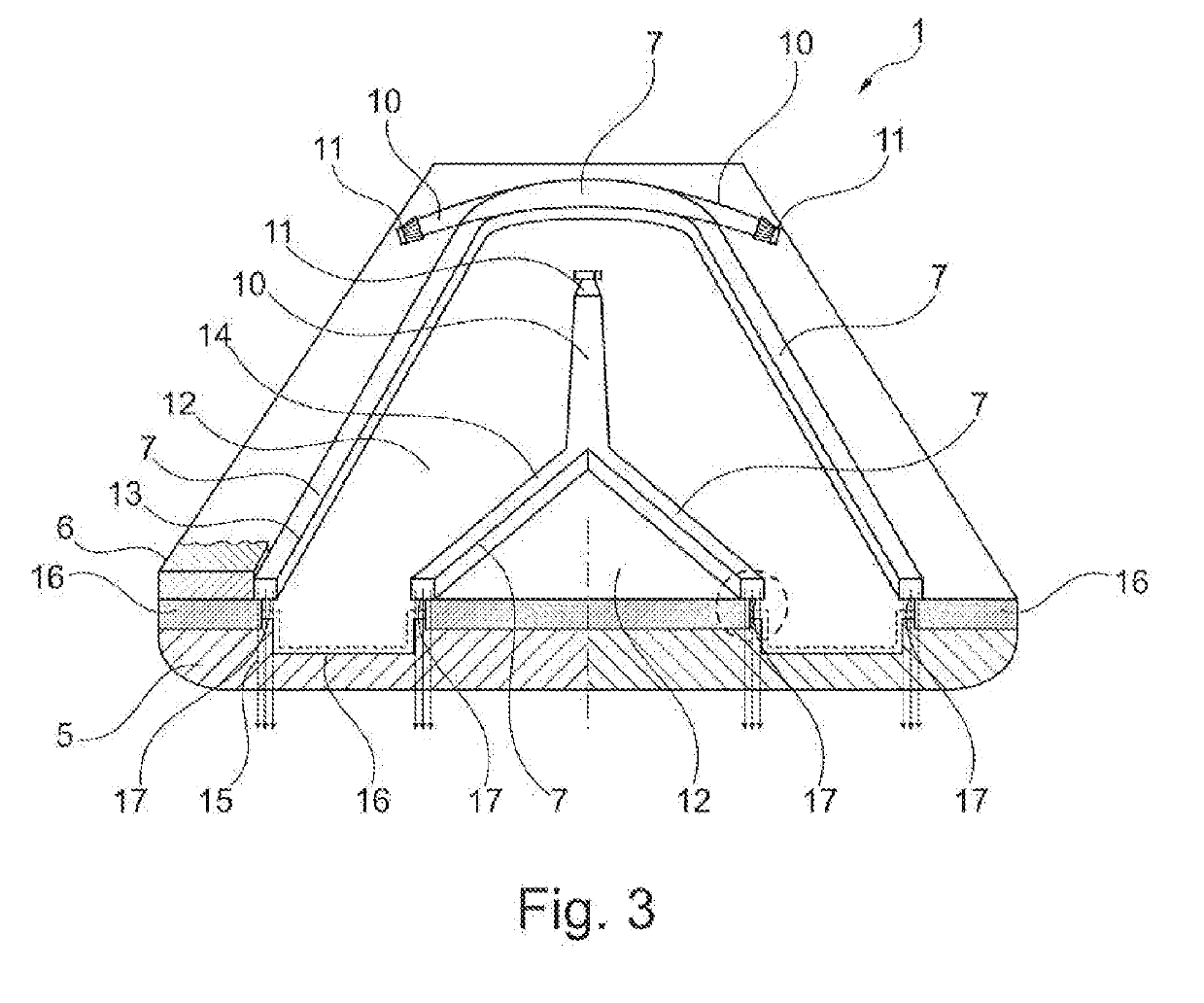
[0024]FIGS. 1 to 5 show, in various illustrations, in each case one exemplary embodiment of an illuminable emblem 1 according to the invention or details thereof, which emblem may be used for example as a cover, as a flap closure element for a lock or as a radome for covering a radar sensor, in particular on the front or on the rear of a motor vehicle. An illuminable emblem of said type may also be used in other ways.

[0025]The illuminable emblem 1 has at least one illuminant which is activatable and deactivatable and / or also controllable in terms of its brightness and / or in terms of its color, such that the emblem is illuminable. Here, the emblem is illuminated in particular from an inner region, such that, viewed from the outside, in particular viewed from the front of the emblem, said emblem is self-illuminating when the at least one illuminant is activated.

[0026]FIG. 1 shows a front view of an illuminable emblem 1, which exhibits substantially a rhomboidal figurative motif 2. Her...


PUM


Abstract

The invention relates to an illuminable emblem, in particular for a motor vehicle, having a housing with a front cover which is at least regionally transparent on a front side, a rear-side housing base, which are connected to one another and enclose a cavity, wherein, in the cavity, there is arranged a light conductor which at least regionally forms webs, which directly adjoin transparent regions of the front cover, for the defined emergence of light from the web of the light conductor into the front cover and through the front cover, wherein the light conductor furthermore has at least one light coupling-in region at which there is arranged at least one illuminant for the coupling-in of light into the light conductor, wherein the light conductor, between the webs, forms free spaces which are filled by the front cover and/or by the housing base.

Description

TECHNICAL FIELD[0001]The invention relates to an illuminable emblem, in particular for a motor vehicle.PRIOR ART[0002]In motor vehicles, emblems in particular on the front end and on the rear end are known, which identify for example the vehicle manufacture or the vehicle type. Such emblems may for example also, as a flap closure element, actuate a lock, or serve as a radome and cover a radar sensor. Here, the known emblems are produced for example as metal plaques or plastic plaques, and are typically not visible or only poorly visible at night.[0003]Recently, there has been interest in illuminating such emblems in order that they are clearly visible even in darkness.[0004]DE 10 2015 220 341 A1 has disclosed an illuminable emblem as a radome for covering a radar sensor. Here, the areal light conductor to the front plate is covered by a plate which is impermeable to light, and the light is introduced in a lateral direction through a diffuser into the front plate and is reflected on ...

Claims


Application Information

Patent Timeline
IPC IPC(8): B60R13/00G09F13/12
CPCB60R13/005G09F13/12G09F2013/044G02B6/0065G02B6/0023F21W2104/00G09F13/0404G09F13/0418F21S43/237F21S43/241F21S43/245G02B6/001G02B6/0021G02B6/0045G09F13/044
Inventor SCHONE, HEIKOBIZAL, ANA
Owner HELLA KG HUECK & CO
Why Eureka
Try Eureka