Illumination system

a technology of illumination system and sconce, which is applied in the field of illumination system, can solve the problems of relatively complicated construction of illumination system, and achieve the effect of lowering the cost of illumination system

Inactive Publication Date: 2010-03-11
SIGNIFY HLDG BV
View PDF9 Cites 50 Cited by
  • Summary
  • Abstract
  • Description
  • Claims
  • Application Information

AI Technical Summary

Benefits of technology

[0021]The light sources and lenses are preferably arranged in a hexagonal structure. This arrangement yields a compact illumination system. In addition, l...

Problems solved by technology

The known illumination system has the drawback that the ...

Method used


Image

  • Illumination system
  • Illumination system
  • Illumination system

Examples


Embodiment Construction

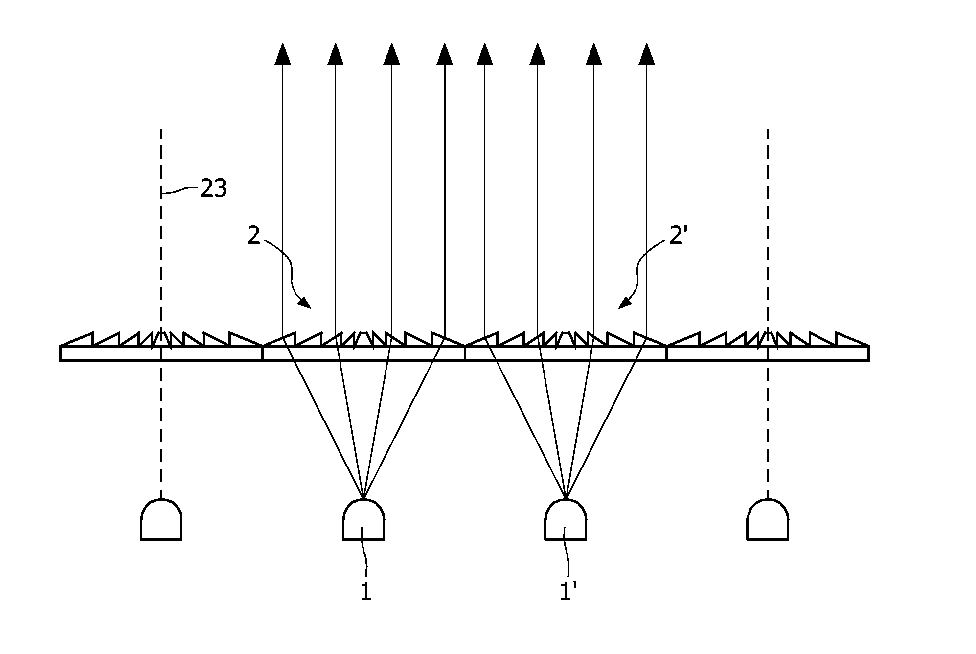
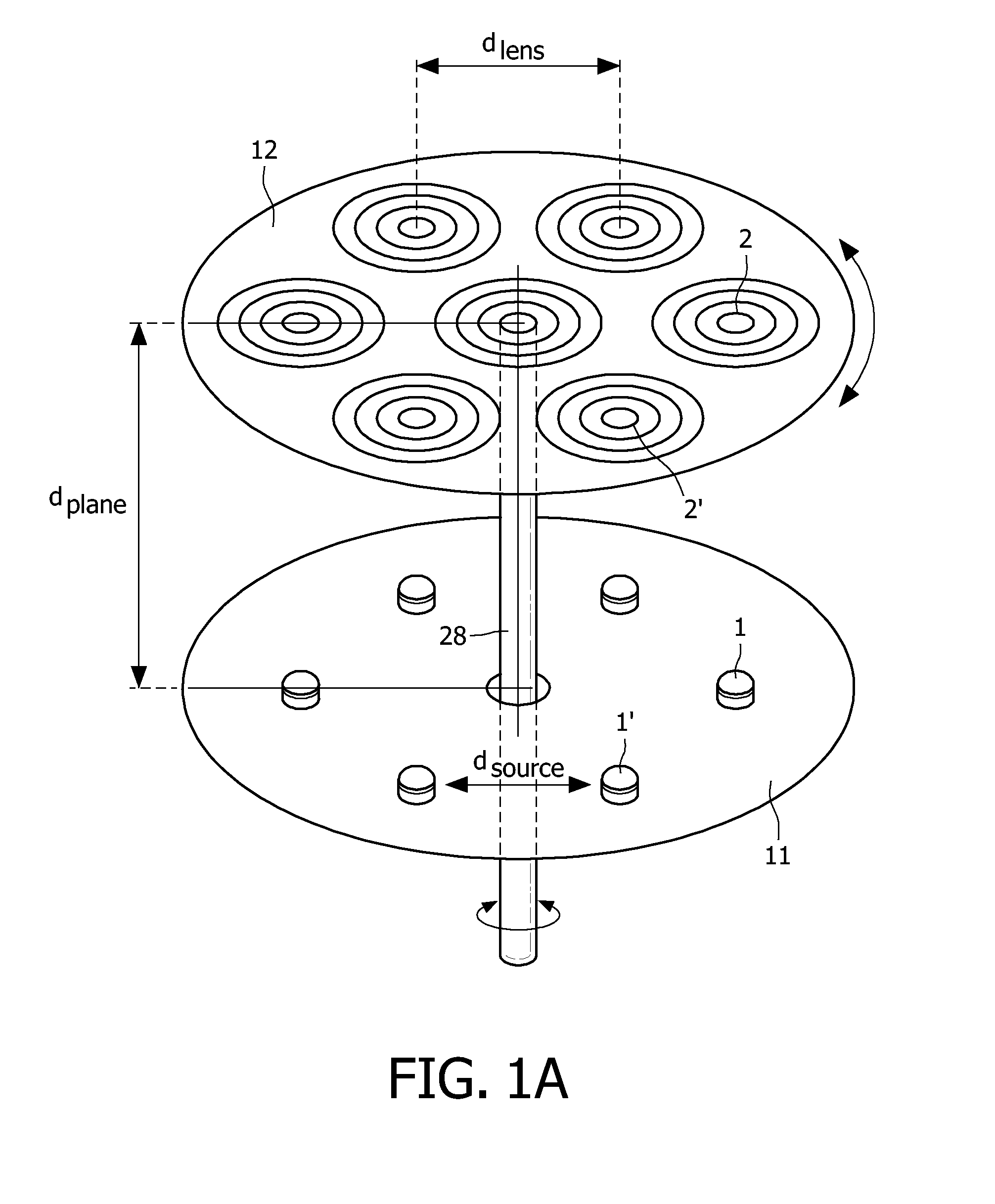
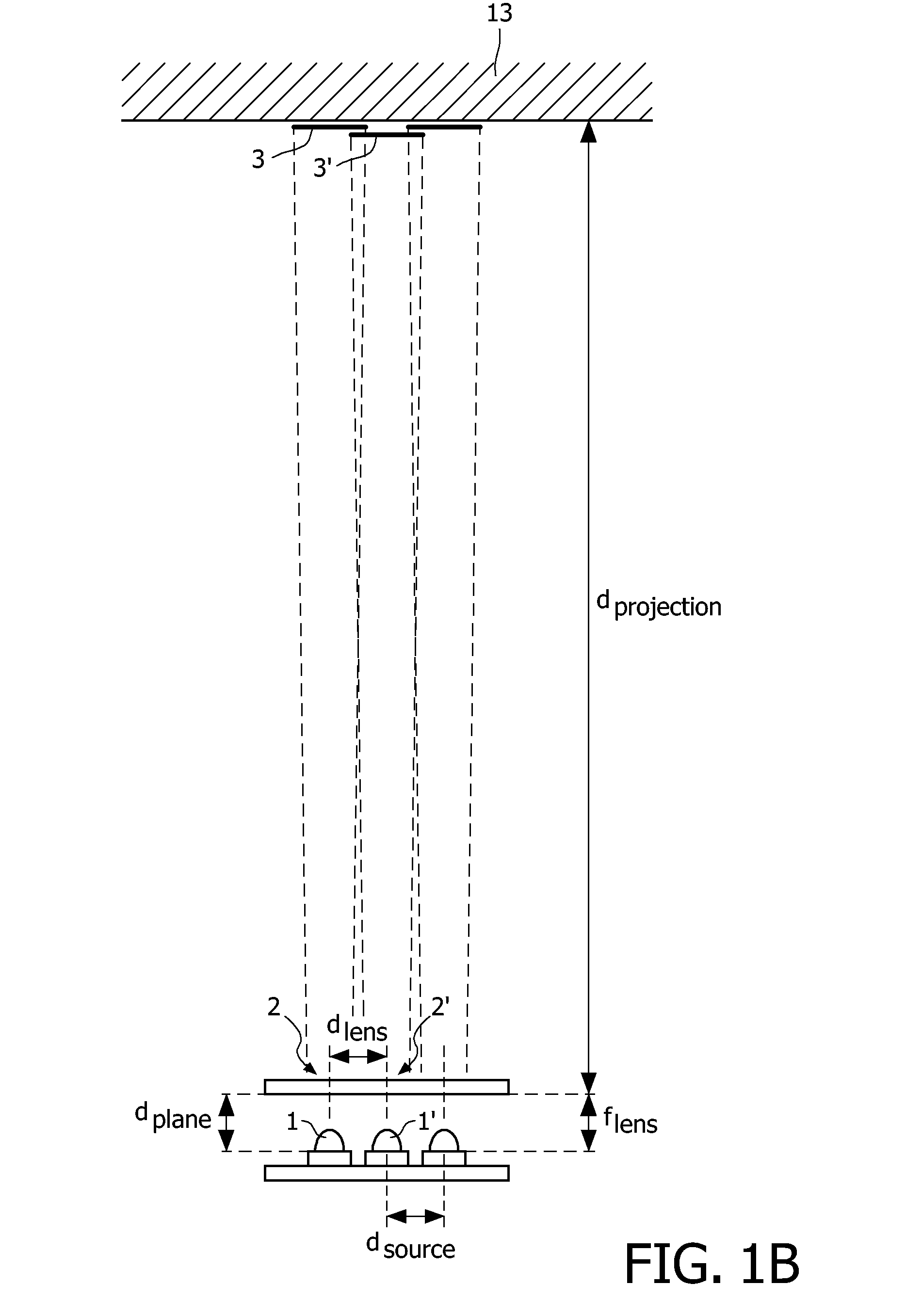
[0040]FIG. 1A is a perspective view of an embodiment of the illumination system according to the invention. In addition, FIG. 1B is a side view of the embodiment of the illumination system as shown in FIG. 1A. The illumination system comprises an array of light sources 1, 1′, . . . arranged in a pre-determined manner in a first plane 11. In the example of FIG. 1A, the light sources 1, 1′, . . . are arranged in a hexagonal structure. The distance between the light sources 1, 1′, . . . is indicated as dsource, dsource representing a characteristic dimension of the spatial arrangement of the light sources 1, 1′, . . . in the first plane 11. In the example of FIG. 1A, the light sources are light-emitting diodes (LEDs). LEDs may be light sources of distinct primary colors such as, for example, the well-known red, green, blue and amber LEDs. Alternatively, the light emitter may have, for example, cyan as a primary color. The primary colors may be either generated directly by the LED chip,...


PUM


Abstract

The illumination system has an array of light sources (1, 1′, . . . ) such as an array of light emitting diodes arranged in a pre-determined manner in a first plane (11), wherein dsource is a characteristic dimension of the spatial arrangement of the light sources in the first plane. An array of associated lenses (2, 2′, . . . ) is arranged in substantially the same pre-determined manner in a second plane (12). Each lens has substantially the same focal distance flens. The array of lenses is provided at a plane distance dplane from the array of light sources. The plane distance dplane is substantially equal to the focal distance flens of the lenses. The illumination system has displacement means for displacing the array of lenses with respect to the array of light sources so as to obtain a plurality of directional light beams projecting spots on a projection plane arranged at a projection distance dprojection from the illumination system, wherein dprojection≧10×dsource and dprojection≧10×dplane.

Description

FIELD OF THE INVENTION[0001]The invention relates to an illumination system comprising an array of light sources and an array of associated lenses.BACKGROUND OF THE INVENTION[0002]Such illumination systems are known per se. They are used, inter alia, for general lighting purposes, such as spot lights, flood lights and for large-area direct-view light-emitting panels applied, for instance, in signage, contour lighting, and billboards. Furthermore, the illumination systems are used as task light.[0003]Generally, such illumination systems comprise a multiplicity of light sources, for instance, light-emitting diodes (LEDs). LEDs may be light sources of distinct primary colors, such as, for example, the well-known red (R), green (G), or blue (B) light emitters. In addition, the light emitter may have, for example, amber (A), magenta or cyan as primary colors. These primary colors may be either generated directly by the light-emitting diode chip, or by a phosphor upon irradiance with ligh...

Claims


Application Information

Patent Timeline
IPC IPC(8): F21V9/00F21V1/00F21K99/00
CPCF21S10/007F21V5/007F21V5/045F21V14/06G02B27/30F21Y2101/02G02B3/08G02B27/0961F21W2131/406F21Y2115/10F21S10/00F21S8/00
Inventor BERGMAN, ANTHONIE HENDRIKCORTENRAAD, HUBERTUS MARIA RENEDE ZWART, SIEBE TJERKVISSENBERG, MICHEL CORNELIS JOSEPHUS MARIE
Owner SIGNIFY HLDG BV
Why Eureka
Try Eureka