Image forming apparatus and control method for same

a technology of image forming apparatus and control method, which is applied in the direction of electrographic process apparatus, instruments, optics, etc., can solve the problems of similar problems, and the description of the positional deviation between the color images on the recording medium

Inactive Publication Date: 2010-03-11
RICOH KK
View PDF18 Cites 35 Cited by
  • Summary
  • Abstract
  • Description
  • Claims
  • Application Information

AI Technical Summary

Benefits of technology

[0016]Exemplary aspects of the present invention have been made in view of the above-described circumstances and provide an image forming apparatus that can effectively contribute to resource saving and cost saving and prevent positional deviation between images formed on a recording medium.
[0018]In one exemplary embodiment, an image forming apparatus includes a first belt member rotatably extended around multiple roller members, a first image forming unit including at least one first color image carrier disposed facing an outer surface of the first belt member, the first image forming unit to form a first image on the at least one first color image carrier, a primary transfer member to transfer the first image formed on the at least one first color image carrier onto the first belt member, a secondary transfer mechanism to transfer the first image formed on the first belt member onto a recording medium at a secondary transfer position, a second image forming unit to form a second image on a separate second image carrier separate from the at least one first color image carrier, the separate second image carrier disposed either upstream or downstream from the secondary transfer position in a direction of conveyance of the recording medium, a direct transfer member to transfer the second image formed on the separate second image carrier directly onto the recording medium at a direct transfer position, a second belt member rotatably extended around multiple roller members to carry the recording medium to the direct transfer position and then to the secondary transfer position, a controller to transfer reference pattern images formed on the at least one first color image carrier and the separate second image carrier onto one of the first belt member and the second belt member, and a first image detector disposed facing one of the first belt member and the second belt member to detect positional deviation of transferred images from the reference pattern images. The controller conveys the reference pattern images to the first image detector, causes the first image detector to detect the reference pattern images, and adjusts one or more image forming conditions of the image forming apparatus to prevent positional deviation of the transferred images from the reference pattern images based on detection results obtained by the first image detector.
[0032]Further in one exemplary embodiment, a control method for the above-described image forming apparatus includes conveying the reference pattern images to the image detector, causing the image detector to detect the reference pattern images, and adjusting one or more image forming conditions of the image forming apparatus to prevent positional deviation of the transferred images from the reference pattern images based on detection results obtained by the image detector.

Problems solved by technology

The different transfer positions of the color images transferred onto the recording medium can easily cause positional deviation between the color images on the recording medium.
However, even when the secondary image transfer position is located downstream from the direct image transfer position in the direction of conveyance of the recording medium, a similar problem to the above-described problem of positional deviation between the color images on the recording medium may still occur.

Method used


Image

  • Image forming apparatus and control method for same
  • Image forming apparatus and control method for same
  • Image forming apparatus and control method for same

Examples


example configuration 1

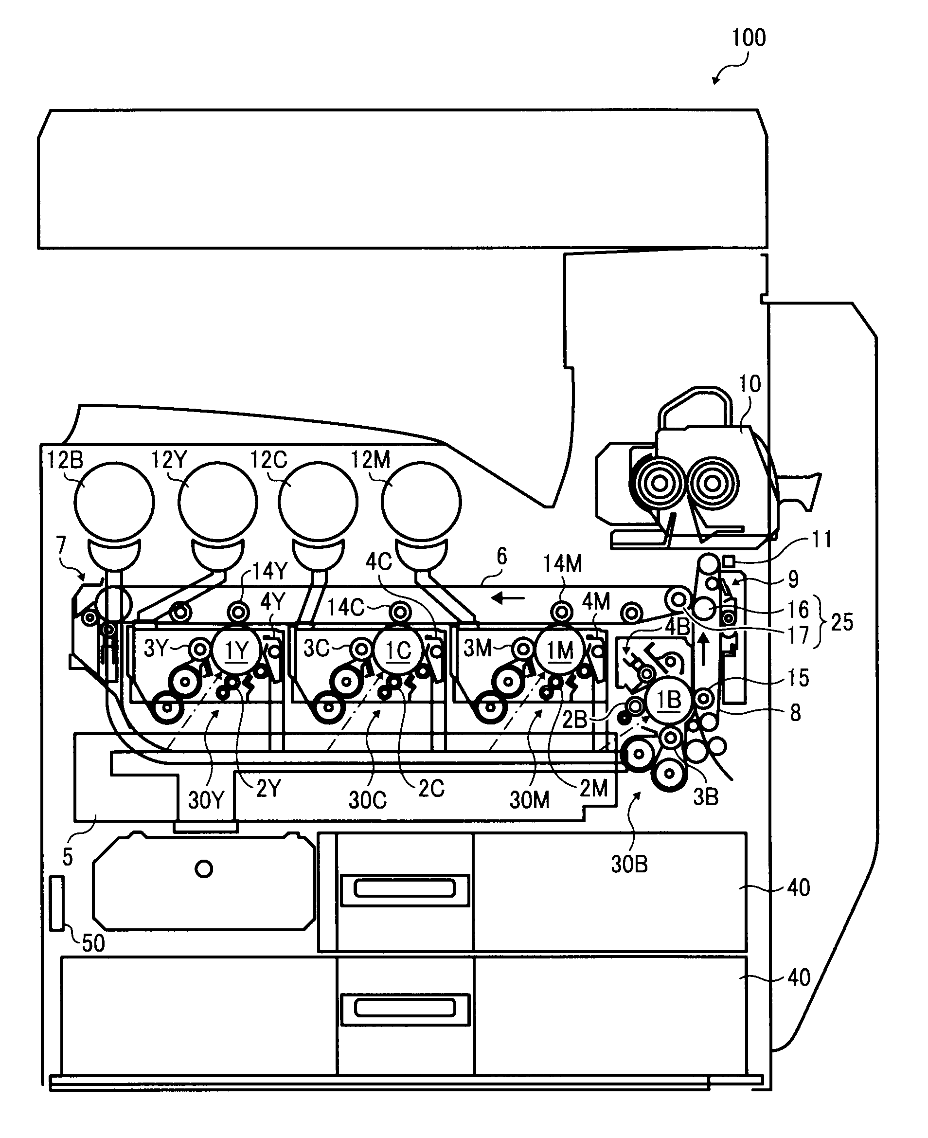
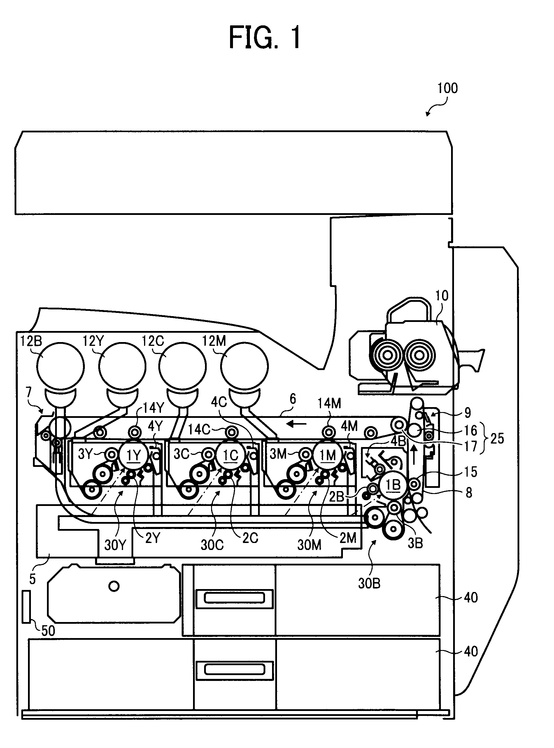
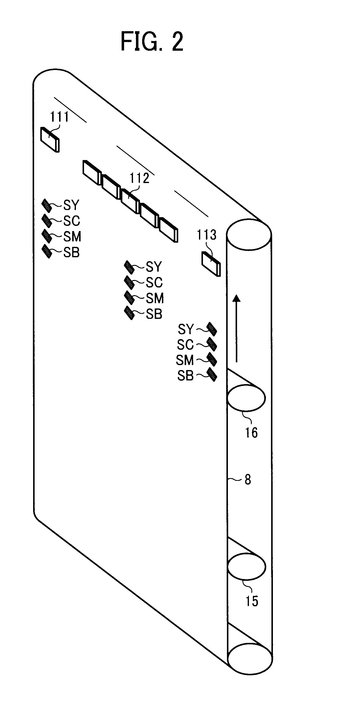
[0128]FIG. 3 illustrates an example configuration of the image forming apparatus 100, which is hereinafter referred to as Example Configuration 1.

[0129]As shown in Example Configuration 1 of FIG. 3, a optical sensor 11 is disposed facing the outer surface of the recording medium conveyance belt 8 in a range of from a separation position where the recording medium is separated from the recording medium conveyance belt 8 to an arranging position of the recording medium conveyance belt cleaning unit 9 in a direction of rotation of the recording medium conveyance belt 8.

[0130]The above-described pattern images are formed on the photoconductors 1Y, 1C, 1M, and 1B and transferred onto the recording medium conveyance belt 8. Then, the pattern images formed on the recording medium conveyance belt 8 are detected by the optical sensor 11.

[0131]The image forming apparatus 100 of Example Configuration 1 further includes a unit case, not shown, to support the recording medium conveyance belt 8. ...

example configuration 2

[0133]FIG. 4 illustrates another example configuration of the image forming apparatus 100, which is hereinafter referred to as Example Configuration 2.

[0134]As shown in Example Configuration 2 of FIG. 4, the optical sensor 11 is disposed facing the outer surface of the recording medium conveyance belt 8 in a range of from a separation position where the recording medium is separated from the recording medium conveyance belt 8 to an arranging position of the recording medium conveyance belt cleaning unit 9 in a direction of rotation of the recording medium conveyance belt 8, which is same as the configuration in Example Configuration 1.

[0135]Different from Example Configuration 1, the image forming apparatus 100 shown in FIG. 4 according to Example Configuration 2 further includes a photoconductor 18. The photoconductor 18 is disposed facing the outer surface of the intermediate transfer belt 6 in a range of from the secondary image transfer nip portion to an arranging position of th...

example configuration 3

[0158]FIG. 8 illustrates another example configuration of the image forming apparatus 100, which is hereinafter referred to as Example Configuration 3.

[0159]Different from Example Configurations 1 and 2, the image forming apparatus 100 according to Example Configuration 3 does not include the optical sensor 11 disposed facing the outer surface of the recording medium conveyance belt 8. As shown in Example Configuration 3 of FIG. 8, the image forming apparatus 100 includes an optical sensor 18 disposed facing the outer surface of the intermediate transfer belt 6 in a range of from the secondary image transfer nip portion to an arranging position of the intermediate transfer belt cleaning unit 7 in the direction of rotation of the intermediate transfer belt 6. The optical sensor 18 serves as a first image detector and a second image detector.

[0160]In Example Configuration 3, the secondary image transfer mechanism 25 transfers the black correction pattern images formed on the recording...


PUM


Abstract

An image forming apparatus includes first and second belt members, at least one color image carrier, a separate image carrier, a primary transfer member, a secondary transfer mechanism, a direct transfer member, a first image detector to detect positional deviation of transferred images from reference pattern images, and a controller to transfer the reference pattern images formed on the at least one color image carrier and the separate image carrier onto the first belt member or onto the second belt member, convey the reference pattern images to the first image detector, cause the first image detector to detect the reference pattern images, and adjust one or more image forming conditions of the image forming apparatus to prevent positional deviation of the transferred images from the reference pattern images based on detection results obtained by the first image detector.

Description

CROSS-REFERENCE TO RELATED APPLICATIONS[0001]The present invention claims priority pursuant to 35 U.S.C. §119 from Japanese Patent Application No. 2008-233072, filed on Sep. 11, 2008 in the Japan Patent Office, and Japanese Patent Application No. 2009-142938, filed on Jun. 16, 2009 in the Japan Patent Office, which are hereby incorporated by reference herein in their entirety.BACKGROUND OF THE INVENTION[0002]1. Field of the Invention[0003]Exemplary embodiments of the present invention generally relate to an image forming apparatus and a control method for same, and more particularly, to an image forming apparatus such as a laser beam printer, a LED printer, a facsimile machine, and the like, and a control method for the above-described image forming apparatus.[0004]2. Discussion of the Related Art[0005]Related-art image forming apparatuses include multiple image forming units to form different single color images that correspond to respective colors including black.[0006]In particul...

Claims


Application Information

Patent Timeline
Patent Type & Authority Applications(United States)
IPC IPC(8): G03G15/16
CPCG03G15/0131G03G2215/0132G03G15/50G03G15/0178
Inventor SUDO, KAZUHISATAKAHASHI, MITSURUKUMA, KAZUOSAKATOH, TSUTOMUFUKAO, TAKESHIKAWAHARA, SHINICHI
Owner RICOH KK
Why Eureka
Try Eureka