Fixing apparatus and image forming apparatus

US20100061778A1Active Publication Date: 2010-03-11SHARP KK

Image

  • Fixing apparatus and image forming apparatus
  • Fixing apparatus and image forming apparatus
  • Fixing apparatus and image forming apparatus

Examples


embodiment 1

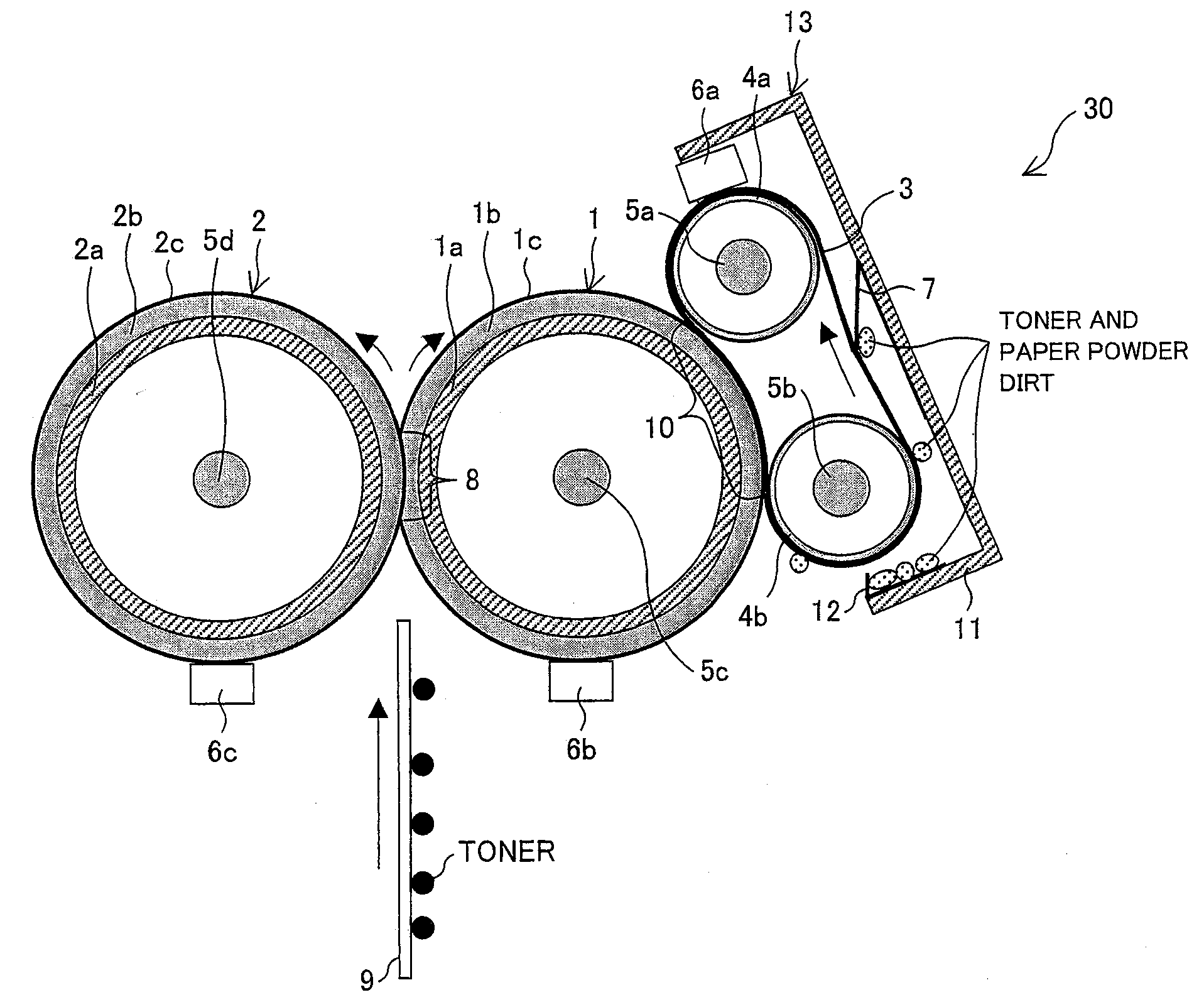
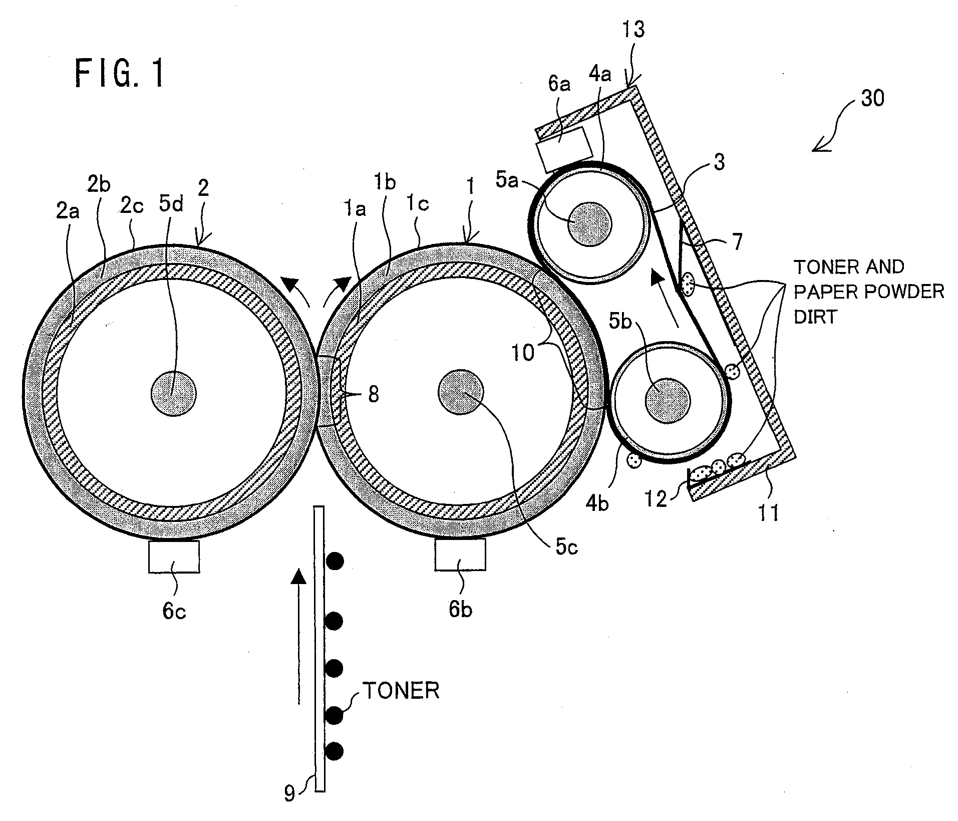
[0054]One embodiment of the present invention is described below. Described in the present invention is a case where the present invention is applied to a color tandem type image forming apparatus for forming a multi-color image or a monochrome image on a recording material (e.g., a recording sheet or a recording film) in accordance with image data transmitted from the outside. Note that an object to which the present invention is applied is not limited to this, but the present invention may be applied to any image forming apparatus as long as it includes a belt fixing type fixing apparatus or an external belt heat type fixing apparatus.

[0055]

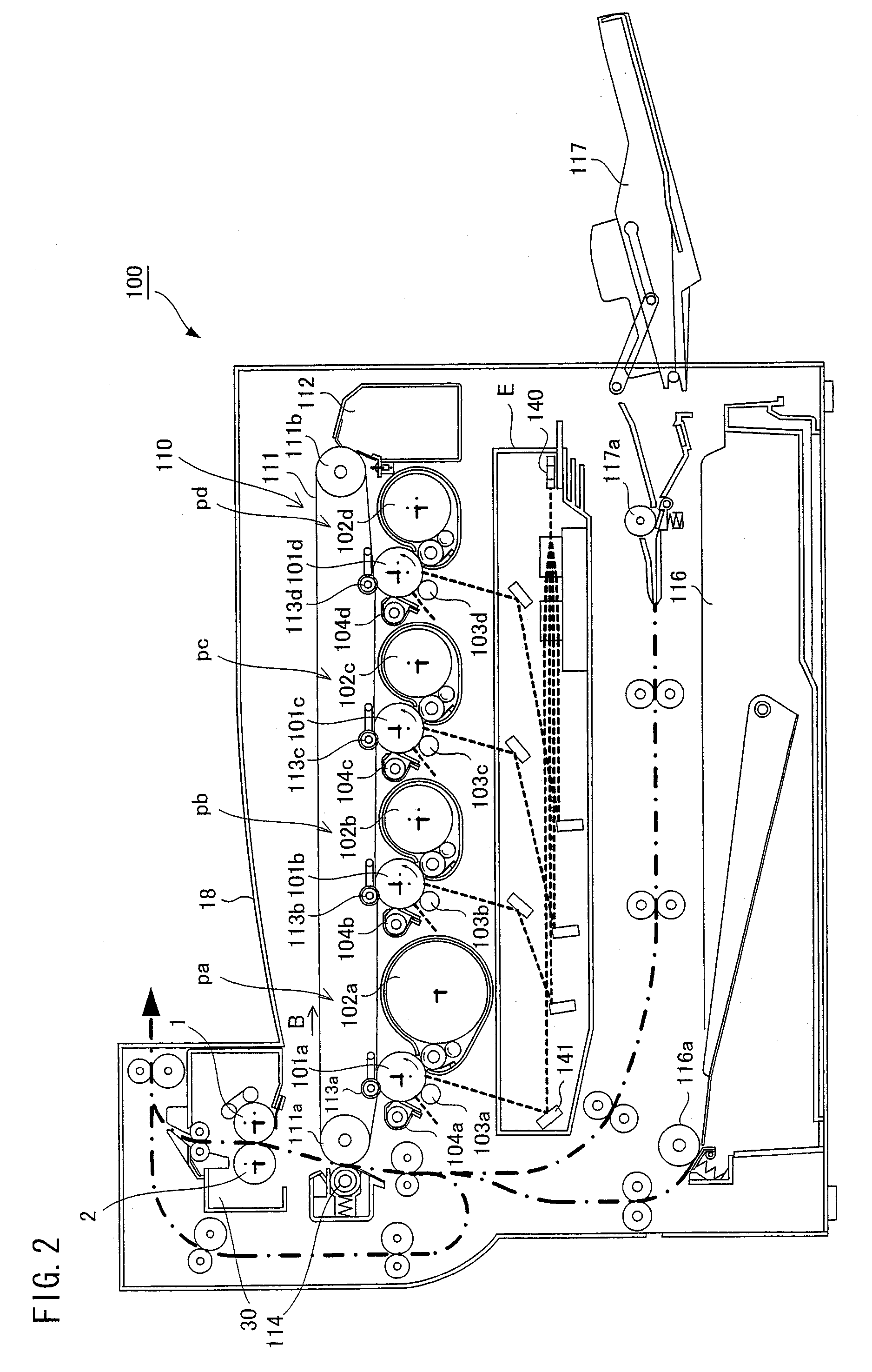
[0056]FIG. 2 is a cross-sectional view schematically illustrating the configuration of an image forming apparatus 100 according to the present embodiment.

[0057]As illustrated in FIG. 2, the image forming apparatus 100 includes: an exposure unit (optical system unit) E; four visible image forming units pa to pd; an intermediate transfer belt uni...

embodiment 2

[0134]The following describes another embodiment of the present invention. For convenience of explanation, members having the same function as those of Embodiment 1 are given the same signs as Embodiment 1, and the explanations thereof are omitted here.

[0135]Described in Embodiment 1 is the case where the present invention is applied to an external belt heat type fixing apparatus. On the other hand, the present embodiment describes a case where the present invention is applied to a belt fixing type fixing apparatus.

[0136]FIG. 12 is a cross-sectional view illustrating the configuration of a fixing apparatus 31 according to the present embodiment. This fixing apparatus 31 is provided in place of the fixing apparatus 30 in the image forming apparatus 100.

[0137]As illustrated in FIG. 12, the fixing apparatus 31 includes a fixing roller (fixing member) 21, a pressure roller (pressure member) 2, a heating roller (suspending roller) 4c, and a fixing belt (endless belt) 23 which is endless....


PUM


Abstract

Provided is a fixing apparatus employing an external heating method in which a scratch on a belt member and slippage of the belt member are prevented. The fixing apparatus includes: a fixing roller; a pressure member pressed against the fixing roller; an endless belt which is rotatably supported and contacts the fixing roller surface for heating the fixing roller; and heating means for heating the endless belt. By passing a recording material through a nip between the fixing roller and the pressure member, the fixing apparatus fixes an unfixed toner image on the recording material on which the unfixed toner image is transferred. The fixing apparatus further includes a cleaning member for removing dirt adhered to a surface of the endless belt by contacting the surface of the endless belt in a region where the endless belt is not supported.

Description

[0001]This Nonprovisional application claims priority under 35 U.S.C. §119(a) on Patent Application No. 2008-228650 filed in Japan on Sep. 5, 2008, the entire contents of which are hereby incorporated by reference.TECHNICAL FIELD[0002]The present invention relates to a fixing apparatus for use in an electrophotographic image forming apparatus, and also relates to an image forming apparatus including the fixing apparatus.BACKGROUND ART [0003]As a fixing apparatus for use in an electrophotographic image forming apparatus such as a copying machine or a printer, a heat roller type fixing apparatus is widely used. In general, the heat roller type fixing apparatus includes a pair of rollers (a fixing roller and a pressure roller) which are pressed against each other. This type of fixing apparatus includes heating means (made of a halogen heater, for example) provided inside both or either one of the pair of rollers. This type of fixing apparatus fixes a toner image in the following manner...

Claims


Application Information

Patent Timeline
11 Mar 2010
Publication
US20100061778A1
IPC
G03G15/20
CPC
G03G15/2025; G03G2215/2019
Inventors
KAGAWA, TOSHIAKI