Auxiliary handle for hand-held power tool

Active Publication Date: 2010-03-18
HILTI AG
View PDF5 Cites 7 Cited by
  • Summary
  • Abstract
  • Description
  • Claims
  • Application Information

AI Technical Summary

Benefits of technology

[0017]Advantageously, the articulation section of the attachment section is likewise provided with counter-locking means with which the locking means of the locking member cooperates in the locking position of the locking member. The

Problems solved by technology

The drawback of the above-described auxiliary handle consists in that for releasing the lag hinge, the engaging each other elements of the locking device should be spaced from each other by at least the heigh

Method used


Image

  • Auxiliary handle for hand-held power tool
  • Auxiliary handle for hand-held power tool
  • Auxiliary handle for hand-held power tool

Examples


Example

[0028]In the drawings, the same parts are designated with the same reference numerals.

DETAILED DESCRIPTION OF THE PREFERRED EMBODIMENT

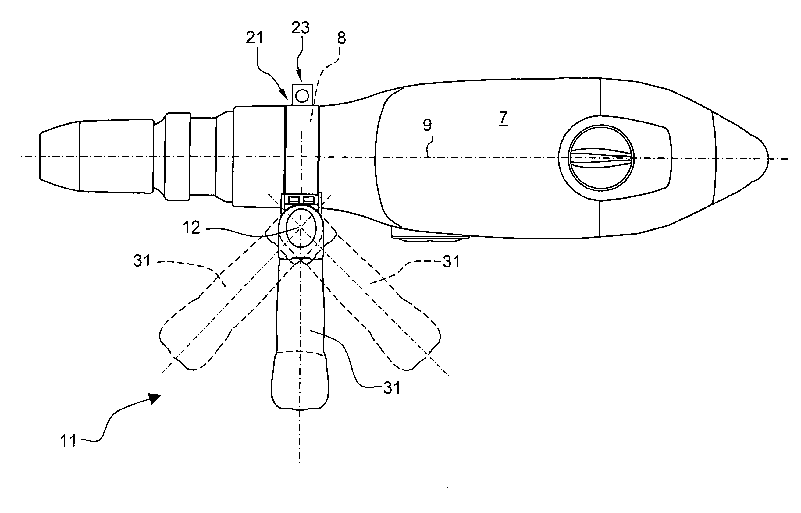
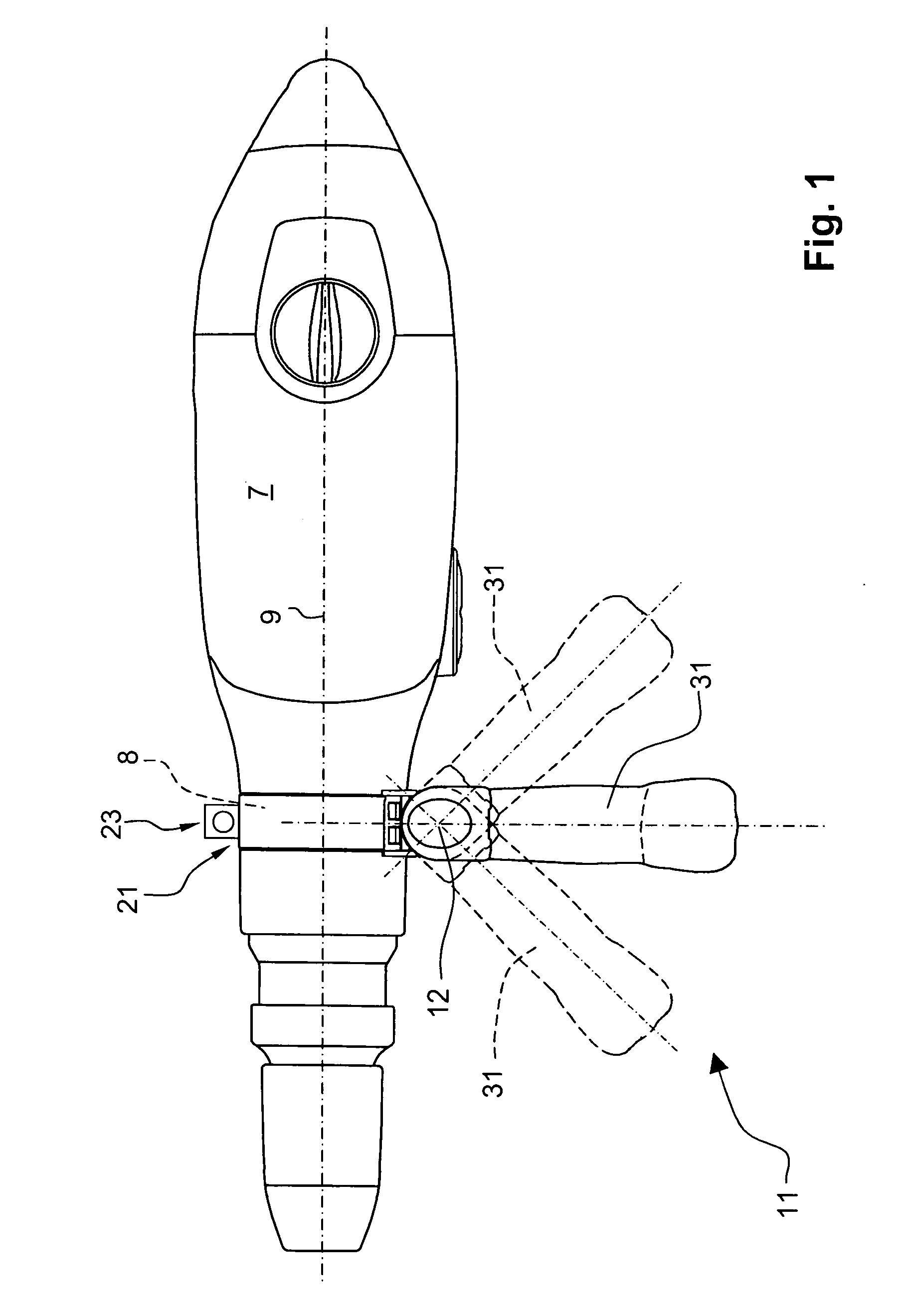
[0029]A hand-held power tool 7, which is shown in FIG. 1, includes an auxiliary handle 11 according to the present invention that is formed as a side handle and is releasably secured on a cylindrical section 8 of the power tool 7. The auxiliary handle 11 has a gripping member 31 for grasping and holding the auxiliary handle 11 and pivotable about a pivot axis 12 toward an operational axis 9 of the power tool 7 to adapt to the gripping position on the power tool 7, when needed.

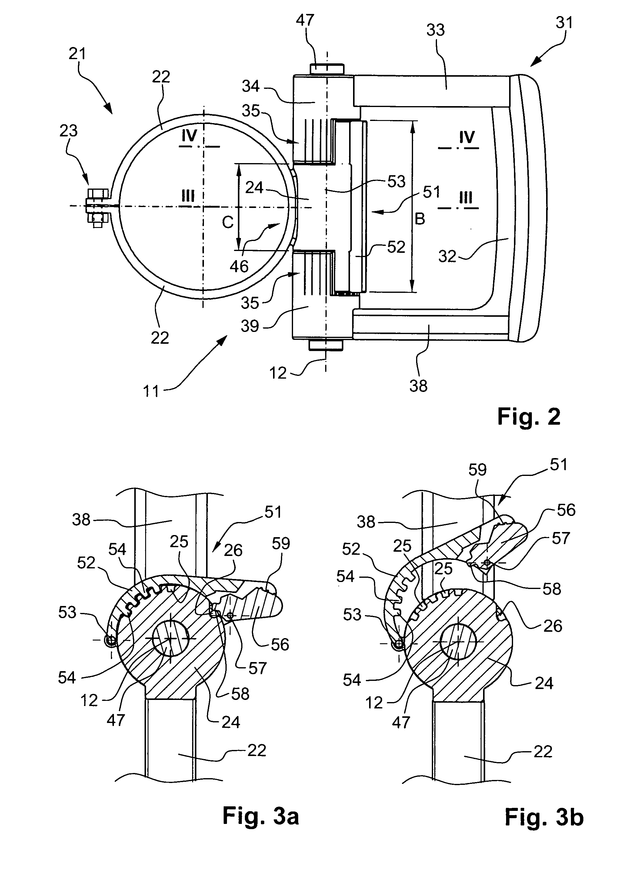
[0030]The auxiliary handle 11, which is shown in detail in FIGS. 2-4b, has an attachment section 21 for securing the auxiliary handle 11 on the power tool 7 and two, pre-loaded against each other, clamping sections 22. The clamping sections 22 are securable on the cylindrical section 8 by a clamping device 23 formed by a clamping screw and a nut. In a loosened position of the cla...


PUM


Abstract

An auxiliary handle for a hand-held power tool (7) includes an attachment section (21) for securing the auxiliary handle (11) on a section (8) of the power tool (7) a gripping member (31) for holding the auxiliary handle (11), a lag hinge (46) provided between the attachment section (21) and the gripping member (34), and including a locking member (52) pivotable about an axis (53) extending parallel to the axis (12) of the lag hinge (46) between its locking position in which it blocks the lag hinge (46), and a release position thereof in which the lag hinge (46) is released.

Description

BACKGROUND OF THE INVENTION[0001]1. Field of the Invention[0002]The present invention relates to an auxiliary handle for a hand-held power tool such as a power drill, a hammer drill or a chisel hammer and includes an attachment section for securing the auxiliary handle on a section of the power tool and having an articulation section, a gripping member for holding the auxiliary handle and having at least one bearing section, a lockable lag hinge provided between the attachment section and the gripping member and having a pivot axis, and a locking device for locking and releasing the lag hinge.[0003]2. Description of the Prior Art[0004]In power tools, auxiliary handles of the type described above are provided, if needed, in form of a side handle mounted, e.g., on a housing section adjacent to a tool holder for guiding the power tool. It is known to form a gripping member of the auxiliary handle pivotable about a pivot axis in order to optimally guide the power tool and to enable diff...

Claims


Application Information

Patent Timeline
IPC IPC(8): B25G1/00
CPCB25F5/026Y10T16/498Y10T16/469Y10T16/4713
Inventor MARTIN
Owner HILTI AG
Why Eureka
Try Eureka