Device for controlling a condensate lift pump, and corresponding capacitive detector and system

a technology of condensate lift and capacitive detector, which is applied in the direction of space heating and ventilation details, heating types, and domestic heating details, etc., can solve the problems of condensate level detection devices still having disadvantages, immobilization in the bottom portion, and overflow of vats, etc., to eliminate mobile mechanical elements, simple and effective, and inexpensive to implement

Active Publication Date: 2010-03-18
SAUERMANN IND
View PDF9 Cites 31 Cited by
  • Summary
  • Abstract
  • Description
  • Claims
  • Application Information

AI Technical Summary

Benefits of technology

[0029]More specifically, an objective of the invention is to provide a technique for controlling a condensate lift pump that is simple and effective, and inexpensive to implement.
[0030]At least according to one embodiment, an objective of the invention is to provide such a technique that enables the need for mobile mechanical elements to be eliminated.

Problems solved by technology

In this type of situation, the condensates are no longer pumped, or are not pumped fast enough, which can thereby result in overflow of the vat 4.
This known type of condensate level detection device nevertheless has disadvantages associated with the impurities (dust, fibers, etc.) initially present in the environment of the system 1 and which are found in the condensates collected in the vat 4.
However, this fouling disrupts the movement of the float 23 inside of the container 20, thereby causing it to be immobilized in the bottom portion of the container 20.
Similarly, these bio-films can disrupt the movement of the float 23.
A disadvantage of this technique is that the fouling and the bio-films can cover the tube containing the sensors and / or disrupt the trajectory of light, preventing or distorting level detections.
Another disadvantage is that, like the preceding technique, it still requires the presence of moving mechanical means, at least for the safety level.
This mechanical means assumes precise and costly assembly, and can still be blocked or seized.
This approach is simpler, but less effective, since the pumping duration is fixed, and can be too long or too short according to the situation.

Method used


Image

  • Device for controlling a condensate lift pump, and corresponding capacitive detector and system
  • Device for controlling a condensate lift pump, and corresponding capacitive detector and system
  • Device for controlling a condensate lift pump, and corresponding capacitive detector and system

Examples


Embodiment Construction

Introduction

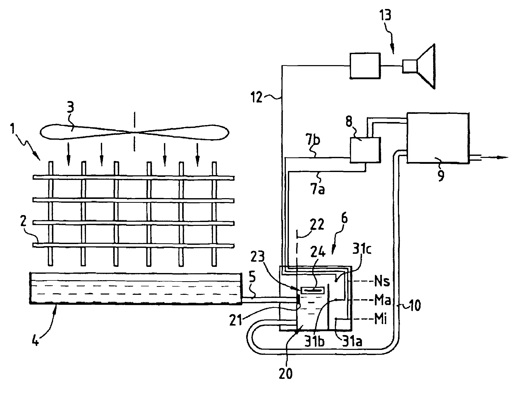
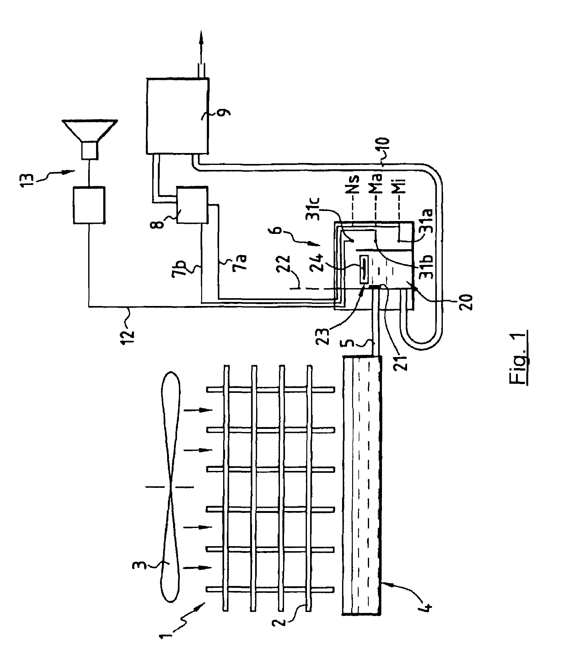
[0062]The invention therefore proposes a new approach to controlling a condensate lift pump, in so-called HVACR (“Heating, Ventilation, Air-Conditioning, Refrigeration”) systems. In some of these systems, of which an example is shown in FIG. 1, already discussed, a condensate lift pump is provided, belonging for example to the group comprising piston pumps, centrifugal pumps, peristaltic pumps, membrane pumps, and so on.

[0063]This pump is associated with a level detector, which can be combined in the same assembly with the pump (so-called one-piece pump) or separated from it (so-called two-piece pump). According to the applications and requirements, the pump and / or the detector can be mounted in, below or next to the air-conditioning unit, as the case may be in a gutter provided for this purpose.

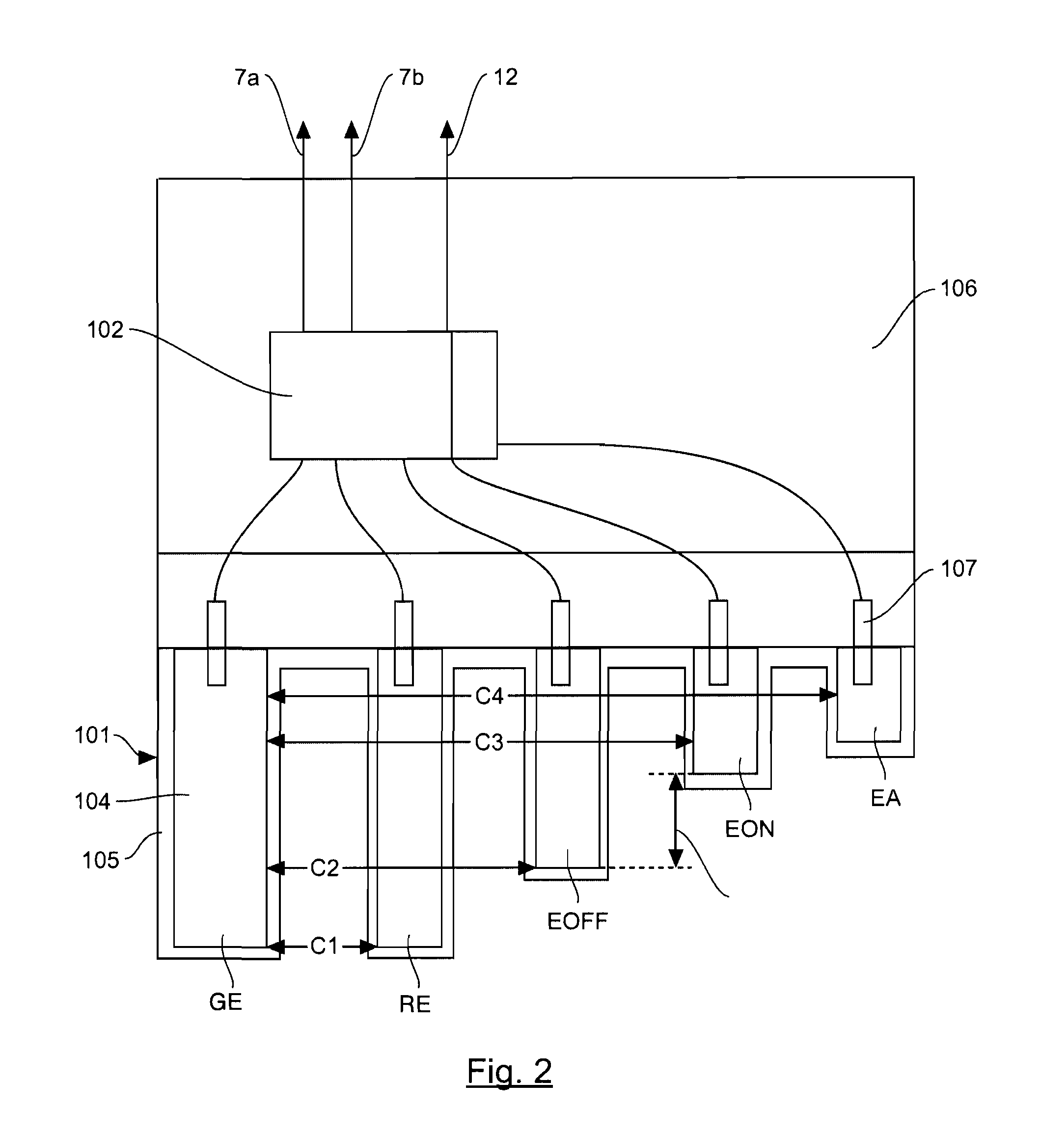
[0064]According to the invention, the detector rests on a capacitive sensor, configured so as to be capable of measuring at least two levels, a first level corresponding, for exa...


PUM


Abstract

The invention relates to a device for controlling a condensate lift pump (9), comprising a means for detecting at least two condensate levels in a container (20), and a means for activating and for stopping said pump (9) according to said levels, in which said detection means comprises a capacitive detector (101) comprising at least three electrodes (GE, RE, EOFF, EON, EA):
    • a ground electrode (GE);
    • a first level detection electrode (EOFF); and
    • a second level detection electrode (EON),
    • and a processing means (102) comprising a means for measuring the capacitance (C2, C3) between the electrodes.
According to the invention, the lengths of said first level detection electrode (EOFF) and second level detection electrode (EON) are defined so as to come into contact with said condensates, when the condensates respectively reach said first level and said second level in said container (20); these electrodes are produced on distinct supports not having a submergible physical continuity between them.

Description

FIELD OF THE INVENTION[0001]The field of the invention is that of controlling liquid or condensate lift pumps, in particular in air conditioning systems, cooling systems, ventilation systems or heating systems.[0002]More specifically, the invention relates to the detection of condensate levels, in a container, so as to control the activation of a pump in such systems.PRIOR ARTInstallation Example[0003]In these various systems or installations, the condensates, which result from condensation of the water vapor present in the ambient air that is cooled, are generally collected in a vat, or more generally in a collection container, which can in some cases be a simple collection panel. It is therefore necessary to remove the collected condensates, so as to prevent, on the one hand, overflow of the collection container and to limit, on the other hand, the risks of bacterial contamination associated with stagnation of the condensates in said container. This can be achieved by means of gra...

Claims


Application Information

Patent Timeline
Patent Type & Authority Applications(United States)
IPC IPC(8): F25D21/02G05D7/00G01R27/26
CPCF04B49/02F04B49/06F04B49/10F04B2207/70G01F23/268F24F13/222F25D21/14G01F23/265F04D15/0218
Inventor CHAUVIN, ANTOINELEZE, FABRICEBAILLON, MICHEL
Owner SAUERMANN IND
Why Eureka
Try Eureka