Manually and Electrically Actuating Toy Gun Structure

a toy gun and electrical actuator technology, applied in the field of manual and electrical actuator toy gun structure, can solve the problems of lack of product competitiveness on the market, lack of enjoyment of one kind of toy gun structure, and inability to completely reverse the position of the gun machine core tube, etc., to achieve the effect of reducing the risk of electrical failure and high viscosity

Inactive Publication Date: 2010-03-18
YANG CHUNG KUAN
View PDF6 Cites 40 Cited by
  • Summary
  • Abstract
  • Description
  • Claims
  • Application Information

AI Technical Summary

Benefits of technology

[0009]The primary objective of the invention is to provide a manually and electrically actuating toy gun structure having both of the manually and electrically actuating methods, and more particularly, to provide a manually and electrically actuating toy gun structure that makes use of an interlocking salient pin furnished at the free end of a resilient cantilever on a first compound gear. By making use of the interlocking salient pin of the resilient cantilever, when the interlocking salient pin rotates in positive direction, it is capable of driving the triggering device to revert back to a positive action and while the interlocking salient pin rotates in reverse direction, it is capable of relieving the catching to assure that the first compound gear and the lower rack of the piston on the triggering device is capable of reverting back to a complete meshing.
[0010]In the second objective of the manually and electrically actuating toy gun structure of the invention, the bottom surface of the second push member being spread with high viscosity grease is exerted by the action of the fourth position-restoring spring. By making use of the hook portion to drive the push-and-pluck rod of the switch of the power supply to slowly slide in x-direction, one is capable of delaying the switch-off of the power supply. In this way, the interlocking salient pin is capable of avoiding instantly stopping action to prevent the meshing between the half-gear of the first compound gear and the lower rack of the piston from mutually catching which may result in the inability of reverting position.
[0011]To achieve the above-mentioned objective, the invention provides a manually and electrically actuating toy gun structure that includes a gun shell, a trigger, a gun machine core tube, and a piston. The control structure includes a first interlocking rod, a first push member, a second interlocking rod, a transmission set, a triggering device, a gun shell, and a push-and-propping-up block. One end of the first interlocking rod has a connecting pin interlocking with the first push member. The other end of the first interlocking rod has a connecting hole connecting to the trigger and being driven to slide along the x-direction. The hole of the first push member is connected to a connecting end of the first interlocking rod and contacts with the push-and-pluck rod of the switch. The power supply of the electric motor is switched on when the first push member is driven by the first interlocking rod to push the push-and-pluck rod. The arcuate surface of the draw bar on the second interlocking rod performs action in corresponding with the interlocking salient pin of the first compound gear. When the power supply of the electric motor is switched on, the interlocking salient pin at the resilient cantilever of the first compound gear in the transmission set performs action making the piston of the triggering device to be driven backward and the gun machine core tube on the triggering device to be driven by the interlocking salient pin to displace backward too that makes the bullets contained in the cartridge drop at the pre-determined position. When the lower rack under the piston separates from the first compound gear, the piston returns back to the original position and pushes out the compressed air to shoot off the bullet. On the other hand, when the power supply of the electric motor is turned off making the first compound gear generate reversed rotation due to the inertial motion, the interlocking salient pin is capable of relieving the catching with the draw bar to make the first compound gear positively mesh with the lower rack.

Problems solved by technology

This kind of structure of the toy gun lacks of enjoyment while one is playing on the gun since it has only the function of a single shooting.
Nevertheless, as far as the current products are concerned, the way of driving exists only in a single state no matter whether it is a manual or electric motor's driving, and there are no such kinds of structure having both the manually and electrical motor's driving types of today.
Consequently, the fact that the pneumatically driving toy gun is unable to function once the compressed air is used up forms a demerit upon usage, thereby it lacks product competitiveness on the market.
Secondly, when it comes to a sudden power off, the electric motor might persistently drive the third compound gear due to the inertial motion to rotate and separate from the pre-determined reverted position.
All of these situations will result in the fact that the thick gear does not completely mesh with the rack and creates catching condition, thereby the gun machine core tube is unable to completely go back to the reverted position.

Method used


Image

  • Manually and Electrically Actuating Toy Gun Structure
  • Manually and Electrically Actuating Toy Gun Structure
  • Manually and Electrically Actuating Toy Gun Structure

Examples


Embodiment Construction

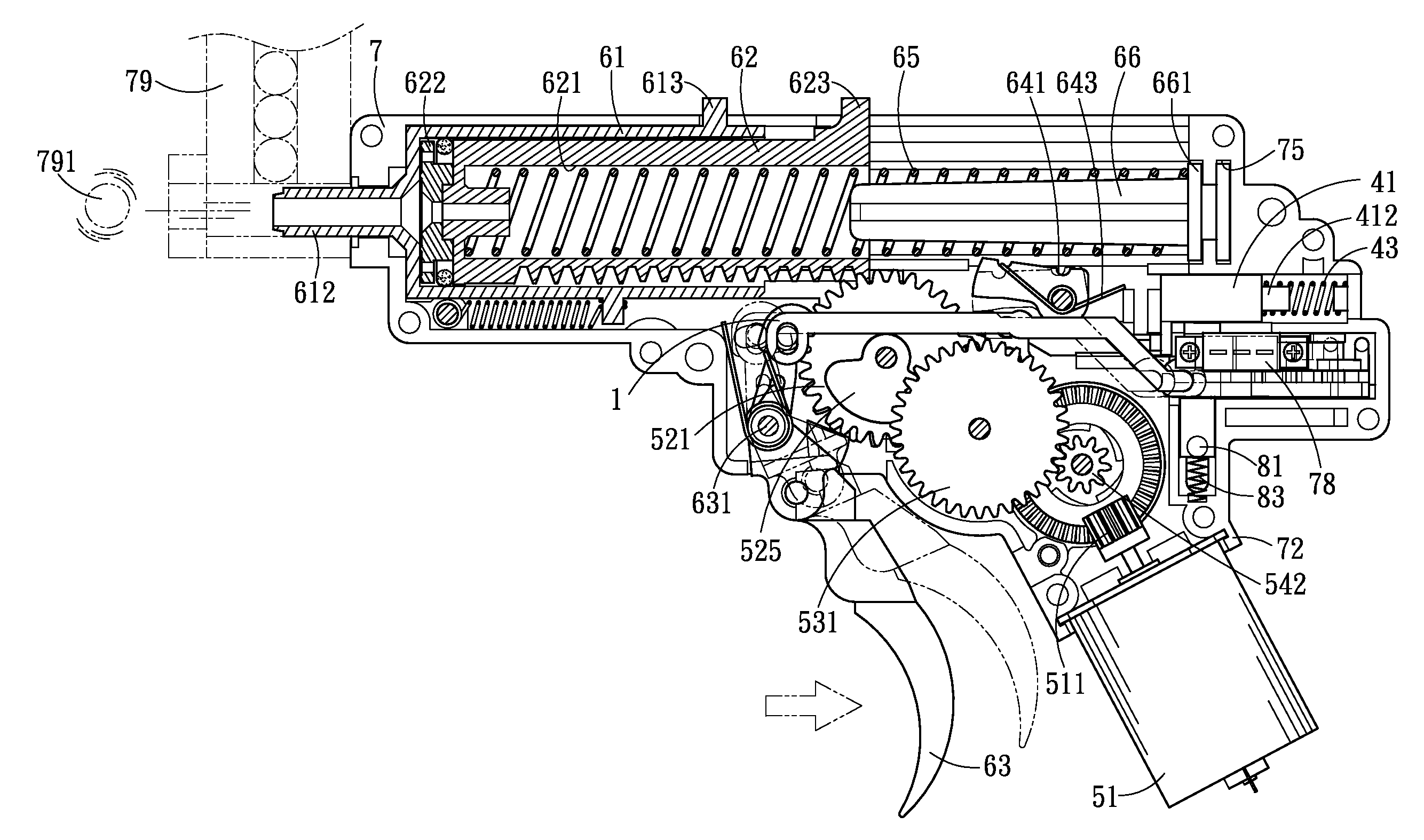
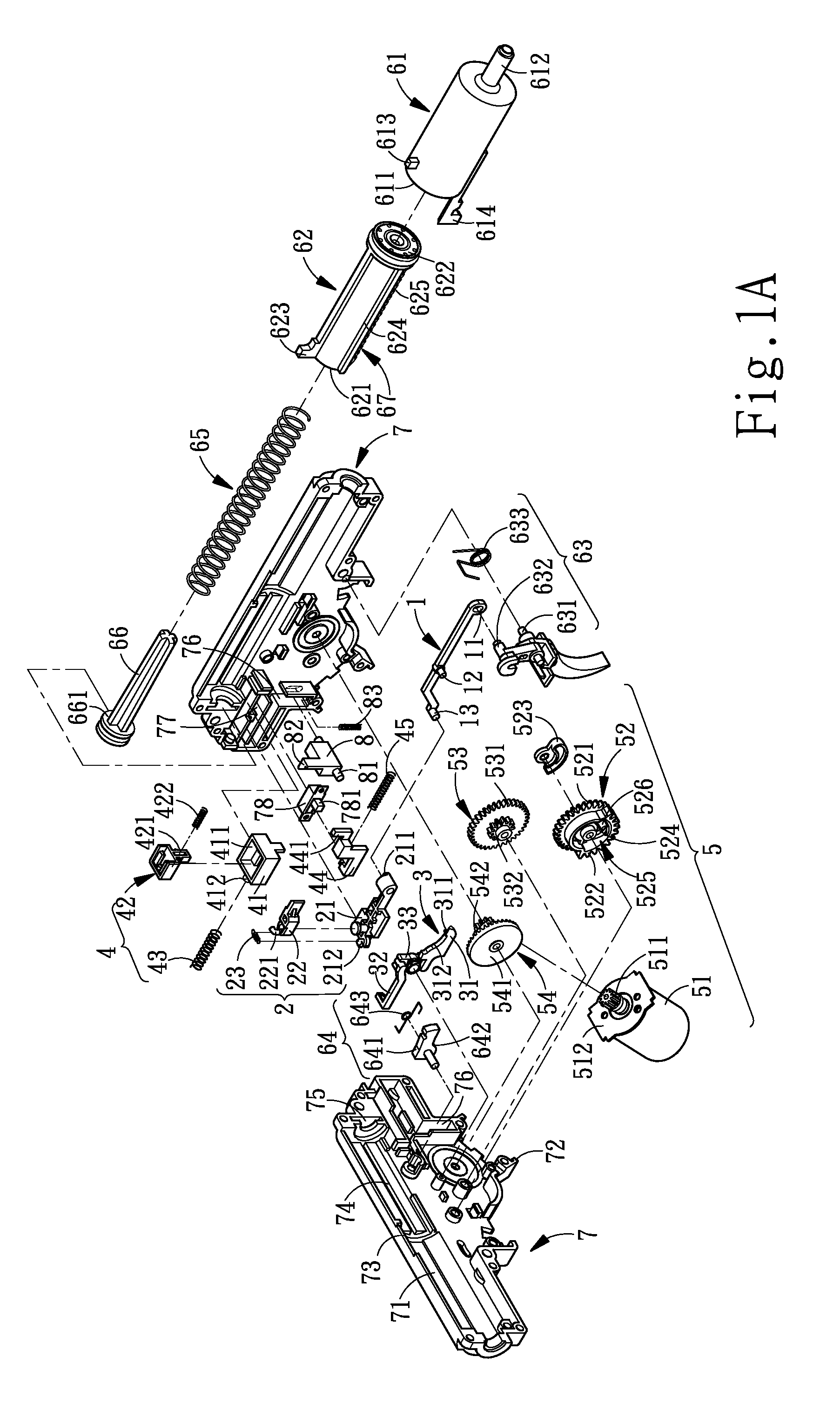
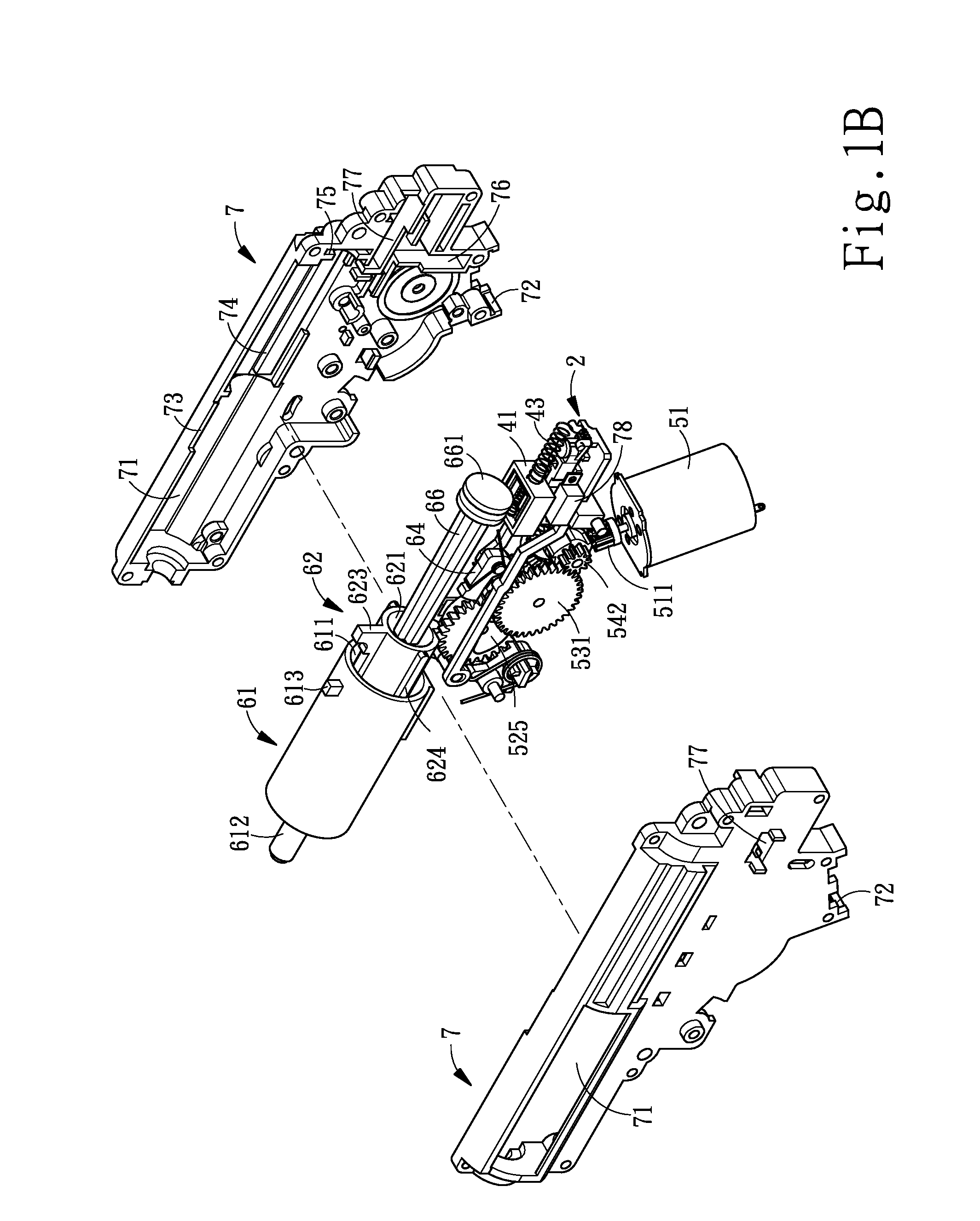
[0026]FIG. 1A is an isometric and exploded view of the manually and electrically actuating toy gun structure of the invention; FIG. 1B is an isometric assembling view of the manually and electrically actuating toy gun structure of the invention. As shown in FIG. 1A, the manually and electrically actuating toy gun structure of the invention, in most parts, being the same as the “Toy Gun Having Dual Actuating Manners” of Taiwan invention patent certificate No. 1264518 (U.S. Pat. No. 7,100,592; China Utility Model Patent No. 20050136485.3; Japan Utility Model Patent No. 2005-9770) includes members of a gun shell (7), a trigger (63), a gun machine core tube (61), and a piston (62) etc. The manually and electrically actuating toy gun structure of the invention further includes a first interlocking rod (1), a first push member (2), a second interlocking rod (3), a second push member (4), a transmission set (5), a triggering device (6), a gun shell (7), and a push-and- -propping-up block (...


PUM


Abstract

A manually and electrically actuating toy gun structure includes a gun shell, a trigger, a gun machine core tube, and a piston. The control structure includes a first interlocking rod, a first push member, a second interlocking rod, a transmission set, a triggering device, a gun shell, and a push-and-propping-up block. One end of the first interlocking rod has a connecting pin interlocking with the first push member. The other end of the first interlocking rod has a connecting hole connecting to the trigger and being driven to slide along the x-direction. The hole of the first push member is connected to a connecting end of the first interlocking rod and is contacted with the push-and-pluck rod of the switch. The power supply of the electric motor is switched on when the first push member is driven by the first interlocking rod to push the push-and-pluck rod. The arcuate surface of the draw bar on the second interlocking rod performs action in corresponding with the interlocking salient pin of the first compound gear. When the power supply of the electric motor is switched on, the interlocking salient pin at the resilient cantilever of the first compound gear in the transmission set performs action making the piston of the triggering device to be driven backward and the gun machine core tube on the triggering device to be driven by the interlocking salient pin to displace backward that makes the bullets contained in the cartridge drop at the pre-determined position. When the lower rack under the piston separates from the first compound gear, the piston returns back to the original position and pushes out the compressed air to shoot off the bullet. On the other hand, when the power supply of the electric motor is turned off making the first compound gear generate reversed rotation due to the inertial motion, the interlocking salient pin is capable of relieving the catching with the draw bar to make the first compound gear positively mesh with the lower rack.

Description

BACKGROUND OF THE INVENTION[0001]1. Field of the Invention[0002]The invention relates to a manually and electrically actuating toy gun structure, and more particularly, to a manually and electrically actuating toy gun structure having both the manually and electrically driving of controlling structure.[0003]2. Description of the Prior Art[0004]Among the current common toy gun products having projectile plastic bullet, there are two types of structure: manual and mechanical structures. The pneumatic type of toy gun makes use of an attached air bottle for providing the high-pressure gas to generate pressure propelled plastic (PP) bullet for projecting off the bullets. However, the mechanical type of toy gun makes use of the resilient spring force released from the compressed spring for propelling a piston to generate high-pressure gas for projecting off the plastic bullets. Both types of toy gun have significant difference in structure since their power sources are different.[0005]As ...

Claims


Application Information

Patent Timeline
Patent Type & Authority Applications(United States)
IPC IPC(8): F41B7/08
CPCF41B11/646F41B11/57F41B11/71
Inventor YANG, CHUNG-KUAN
Owner YANG CHUNG KUAN
Why Eureka
Try Eureka