LED drive circuit

Active Publication Date: 2010-03-18
MURATA MFG CO LTD
View PDF7 Cites 3 Cited by
  • Summary
  • Abstract
  • Description
  • Claims
  • Application Information

AI Technical Summary

Benefits of technology

[0007]Accordingly, preferred embodiments of the present invention provide an LED drive circuit that can su

Problems solved by technology

This may result in self-heating of the tempera

Method used


Image

  • LED drive circuit
  • LED drive circuit
  • LED drive circuit

Examples


first preferred embodiment

[0032]Hereafter, working examples of a preferred embodiment of the present invention will be described.

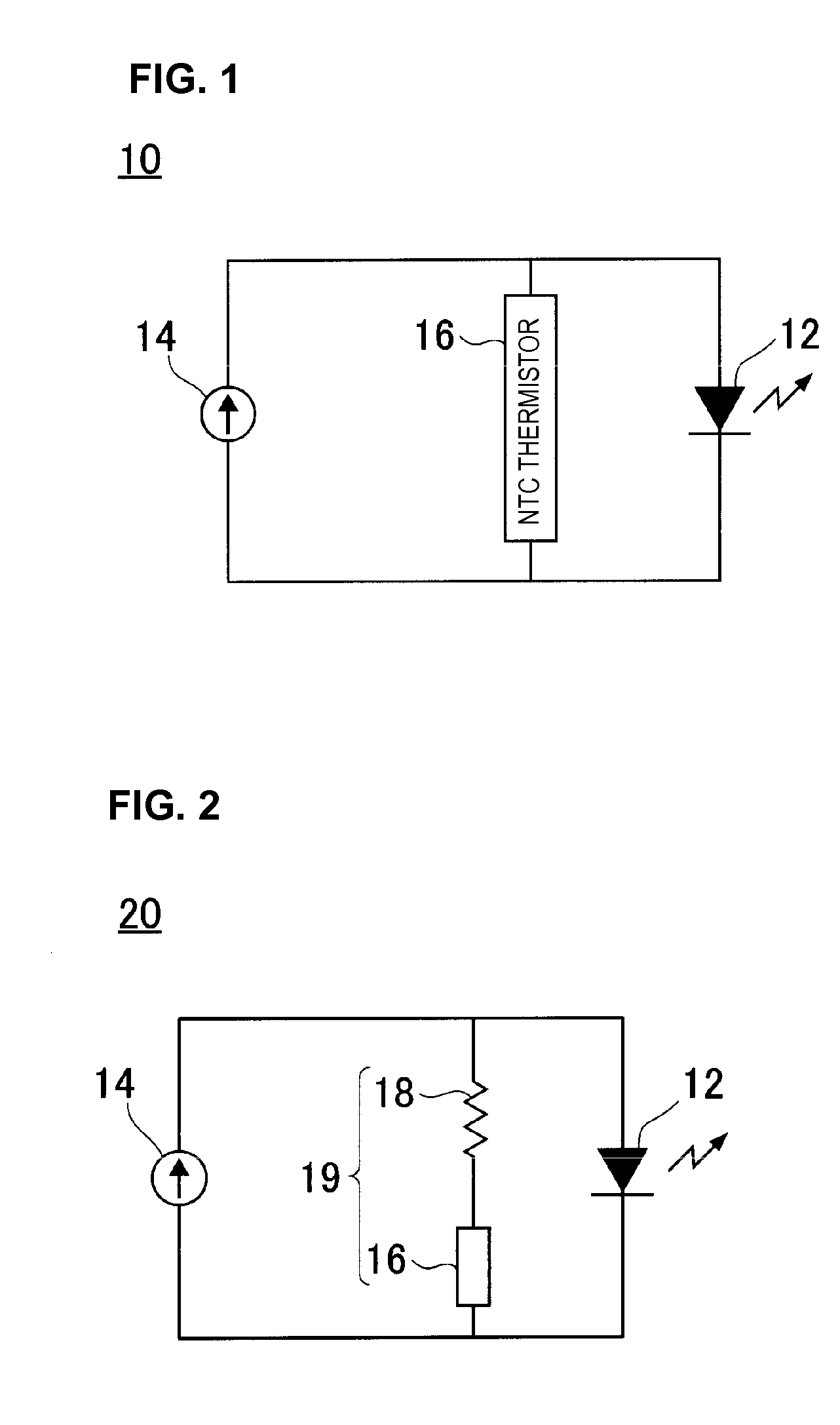
[0033]The LED drive circuit 10 shown in FIG. 1 was formed using an LED element manufactured by the Nichia Corporation, NTSSW008CT, as the LED element 12 and an NTC thermistor manufactured by Murata Manufacturing Co., Ltd., NCP15XW222J03RC (25° C. resistance value 2.2 kΩ±5%, B constant (25 / 50° C.) 3950K±3%), as the temperature sensing element 16. Assuming that the output current of the constant-current output unit 14 is 20 mA, a current flowing into the LED element 12 in the LED drive circuit 10 is shown in FIG. 3. In FIG. 3, a solid line indicates the temperature characteristic of the allowable forward current of the LED element 12 and solid circles indicate a current flowing into the LED element 12.

[0034]As is understood from FIG. 3, the current flowing into the LED element 12 varies while taking a shape according to the temperature characteristic of the allowable forward current ...

second preferred embodiment

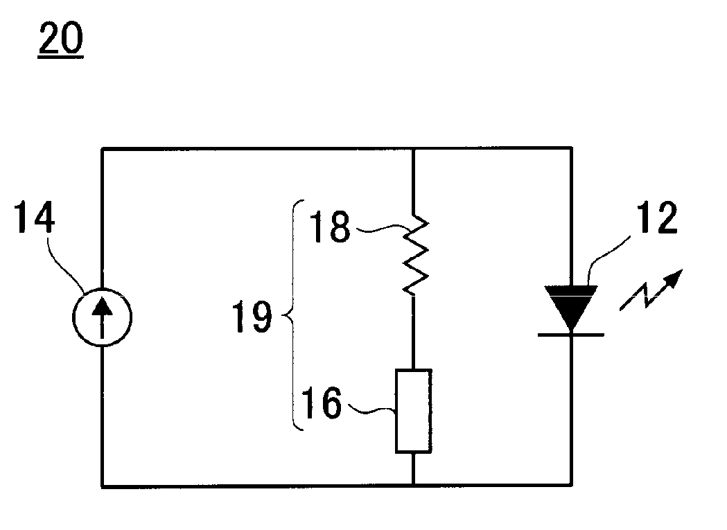
[0036]The LED drive circuit 20 shown in FIG. 2 was formed using an LED element manufactured by the Nichia Corporation, NTSSW008CT, as the LED element 12, an NTC thermistor manufactured by Murata Manufacturing Co., Ltd., NCP15XQ102J03RC (25° C. resistance value 1 kΩ±5%, B constant (25 / 50° C. 3650K±2%), as the temperature sensing element 16, and a fixed resistance having a resistance value of 35Ω±5% as the fixed resistance 18. Assuming that the output current of the constant-current output unit 14 is 35 mA, a current flowing into the LED element 12 in the LED drive circuit 20 is shown in FIG. 4. In FIG. 4, a solid line indicates the temperature characteristic of the allowable forward current of the LED element 12 and solid circles indicate a current flowing into the LED element 12.

[0037]By using the temperature sensing element 16 and connecting the fixed resistance 18 to the temperature sensing element 16 in series, the temperature change rate of the combined resistance value of this ...


PUM


Abstract

An LED drive circuit that sufficiently exhibits the performance of an LED element to obtain a favorable luminance at room temperature, includes a constant-current circuit including an LED element, a constant-current output unit, and a temperature sensing element having a negative resistance-temperature coefficient. The LED element is connected to the constant-current output unit in series. The constant-current output unit is connected to the LED element in parallel. Due to changes in the resistance value of the constant-current output unit caused by changes in temperature, the value of a current passing through the LED element is increased at room temperature and the value of a current passing through the temperature sensing element is reduced at high temperature.

Description

BACKGROUND OF THE INVENTION[0001]1. Field of the Invention[0002]The present invention relates to an LED drive circuit and, in particular, to an LED drive circuit for driving an LED element, for example, used as the backlight of the liquid crystal screen of a cell phone, a portable game machine, or the like.[0003]2. Description of the Related Art[0004]An LED element is used as a lighting element, for example, in the backlight of a traffic signal or a liquid crystal display. Also, in recent years, an LED element has been used in the backlight of the liquid crystal screen of a small-size, portable apparatus, such as a cell phone or a portable game machine. As a drive circuit for an LED element in a small-size, portable apparatus as described above, there has been disclosed an LED drive circuit that includes a booster circuit for boosting the voltage by switching the output of a battery and a constant-current circuit for driving an LED element at a constant current and drives the LED el...

Claims


Application Information

Patent Timeline
IPC IPC(8): H05B41/36H05B44/00H01L33/00
CPCH05B33/0821H05B45/40
Inventor ITO, HIROMASAKITAMURA, YOSHINORI
Owner MURATA MFG CO LTD
Why Eureka
Try Eureka