
Method for pulsed charging of a battery in an autonomous system comprising a supercapacitance

a technology of supercapacitance and autonomous system, which is applied in the direction of secondary cell charging/discharging, electric vehicles, electrical apparatus, etc., can solve the problems of prohibitive cost of a conventional power supply by cable, limited power and energy generated by intermittent power sources such as photovoltaic panels or wind-power generators, etc., and achieves the effect of convenient implementation

Inactive Publication Date: 2010-03-18
COMMISSARIAT A LENERGIE ATOMIQUE ET AUX ENERGIES ALTERNATIVES
View PDF10 Cites 28 Cited by
  • Summary
  • Abstract
  • Description
  • Claims
  • Application Information

AI Technical Summary

Benefits of technology

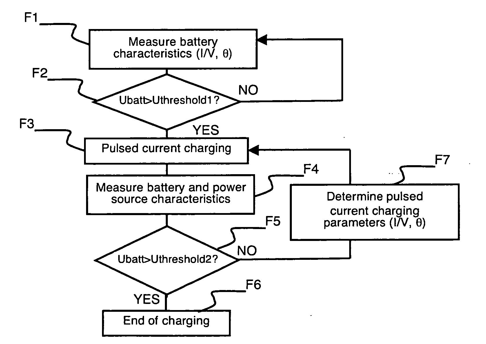
[0005]The object of the invention is to provide a method that is easy to implement, that is compatible energy-wise with pulsed current end-of-charging and that ensures a long lifetime of the battery.
[0010]limiting the value of the battery charging current, at the next current pulse, to a value lower than said maximum current threshold by controlling the closing time of the second electronic switch.

Problems solved by technology

These autonomous systems are often installed in isolated places which are difficult to access for which the cost of a conventional power supply by cable would be prohibitive.
However the power and energy able to be generated by intermittent power sources such as photovoltaic panels or wind-power generators are limited.

Method used


Image

  • Method for pulsed charging of a battery in an autonomous system comprising a supercapacitance
  • Method for pulsed charging of a battery in an autonomous system comprising a supercapacitance
  • Method for pulsed charging of a battery in an autonomous system comprising a supercapacitance

Examples


Embodiment Construction

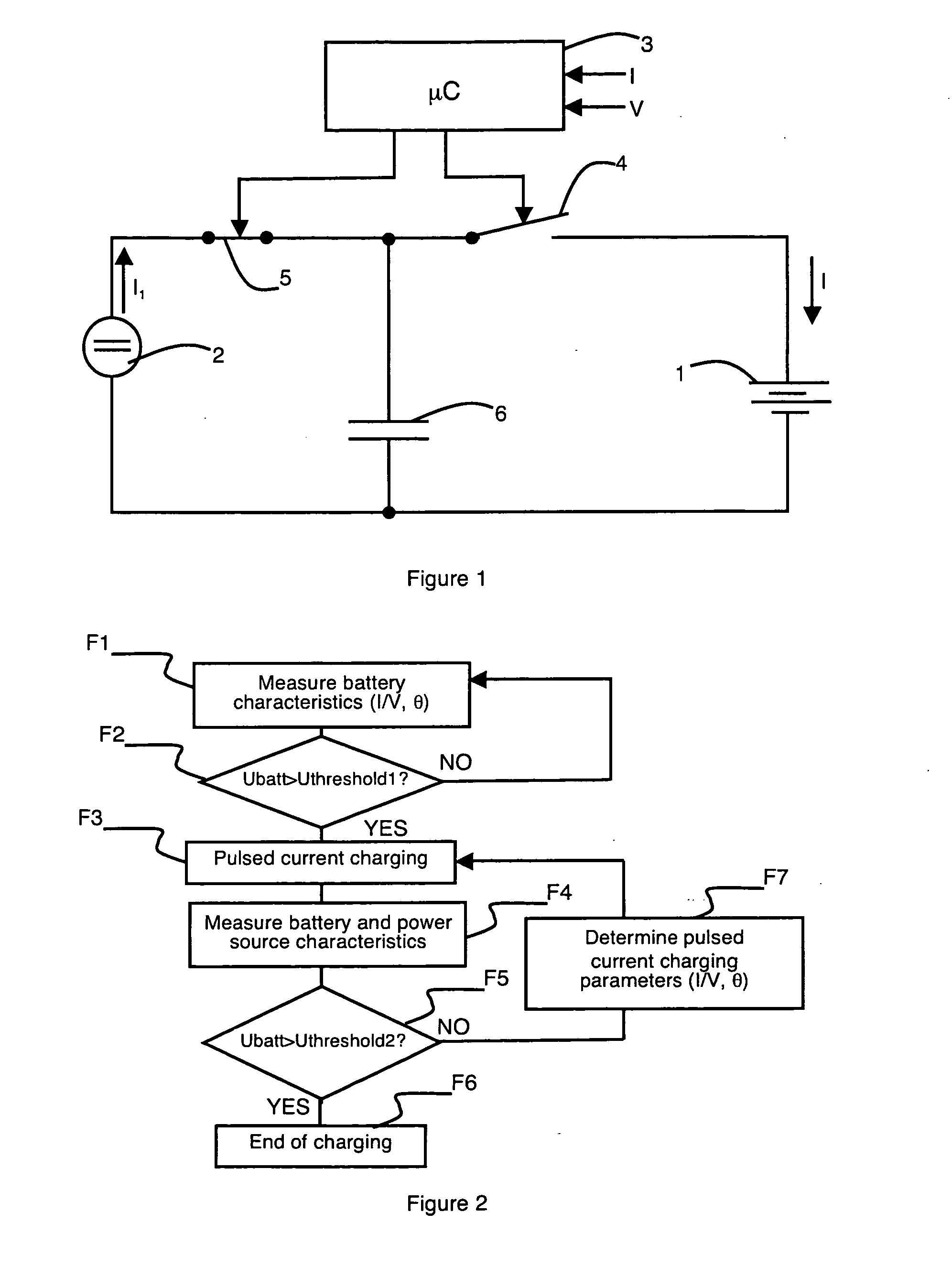
[0017]As illustrated in FIG. 1, the autonomous system comprises at least one battery 1 constituting a power storage element, an intermittent power source 2 and a charging control circuit 3 comprising means for managing charging and end of charging. First 4 and second 5 electronic switches are connected in series between intermittent power source 2 and battery 1. Opening and closing of electronic switches 4, 5 are controlled by charging control circuit 3 via integrated control means.

[0018]Battery 1 is for example a lead or nickel battery and in more general manner a battery with an aqueous electrolyte.

[0019]During its operating periods, intermittent power source 2 delivers a direct current I1 which depends on the outside environment.

[0020]The system also comprises an intermediate power storage element formed by a supercapacitance 6. Supercapacitance 6 is connected in parallel with power storage element 1 via a first electronic switch 4 and in parallel with the intermittent power sour...


PUM


Abstract

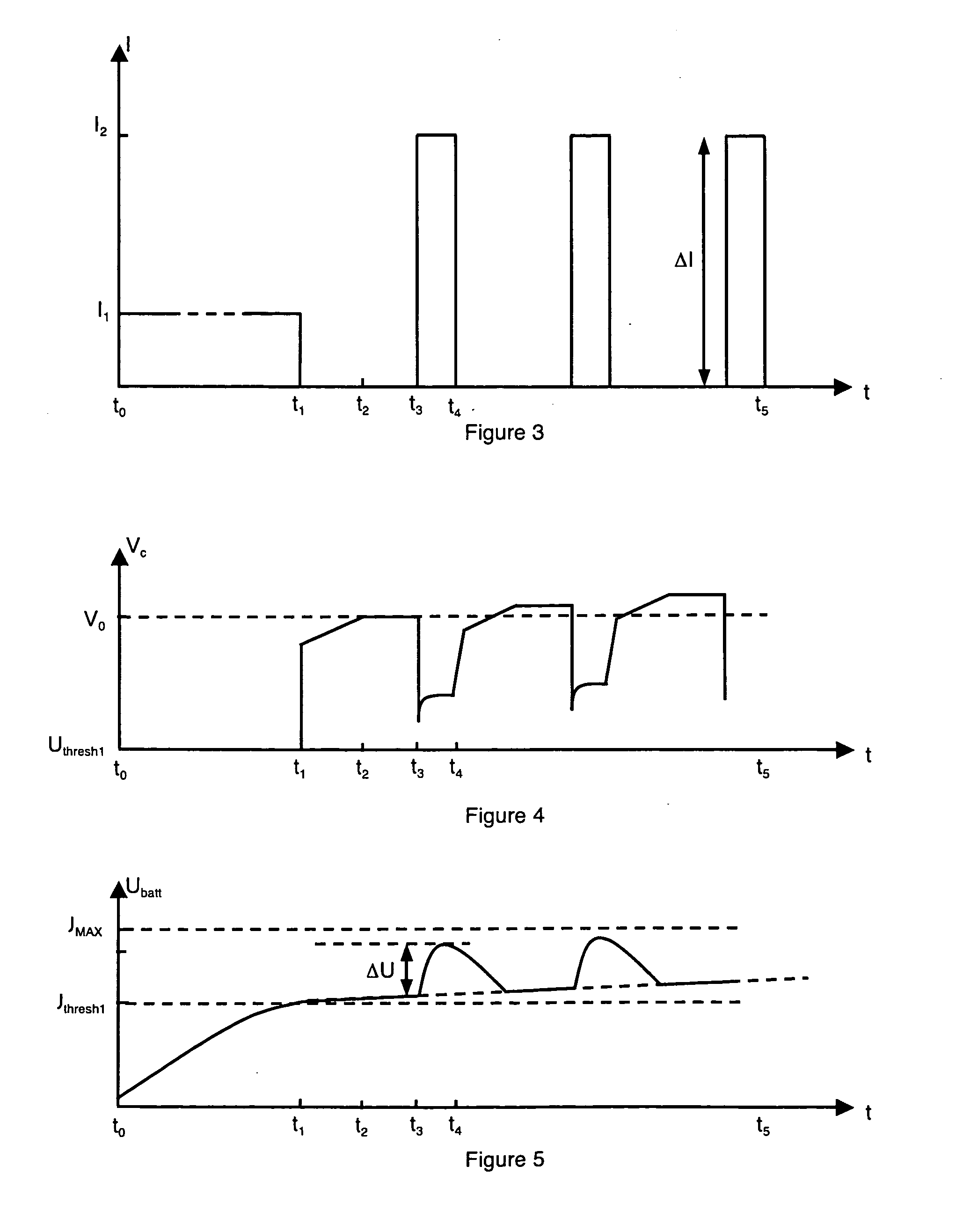
The autonomous system comprises an intermittent power source delivering a direct current. A supercapacitance is connected in parallel with the battery and the power source respectively via a first switch and a second switch. Charging of the battery comprises pulsed current charging managed by a control circuit. During a current pulse, the amplitude of the current and the amplitude of the voltage increase at the terminals of the battery are measured. The dynamic internal resistance of the battery is determined from said amplitudes. A maximum acceptable current threshold is determined according to a maximum voltage threshold, to said dynamic internal resistance and to the no-load voltage at the battery terminals. At the next current pulse, the value of the charging current is limited by controlling the closing time of the second switch.

Description

BACKGROUND OF THE INVENTION[0001]The invention relates to a method for charging a battery of an autonomous system by means of an intermittent power source delivering a direct current, the method comprising at least one phase of charging at pulsed current managed by a charging control circuit.STATE OF THE ART[0002]Autonomous systems supplied by intermittent power sources, for example by photovoltaic panels or generators of wind-power type, are called on to develop. These autonomous systems are often installed in isolated places which are difficult to access for which the cost of a conventional power supply by cable would be prohibitive. For this type of configuration, optimizing maintenance and autonomy is of paramount importance to enable a large reduction of operating costs to be achieved.[0003]Performing the final step of charging a battery by means of a pulsed current has proved its worth from the electrochemical standpoint. Indeed, by adapting the current value, the charging tim...

Claims


Application Information

Patent Timeline
IPC IPC(8): H02J7/00
CPCH01M10/06H01M10/4264H02J7/35H02J7/0093H02J7/345H01M10/44H02J7/00711Y02E60/10
Inventor LABRUNIE, ANTOINEDELAILLE, ARNAUDGENIES, SYLVIE
Owner COMMISSARIAT A LENERGIE ATOMIQUE ET AUX ENERGIES ALTERNATIVES
Learn More