Wireless terminal and handover method of wireless terminal

Inactive Publication Date: 2010-03-18
NEC CORP
View PDF3 Cites 17 Cited by
  • Summary
  • Abstract
  • Description
  • Claims
  • Application Information

AI Technical Summary

Benefits of technology

[0008]The present invention can reduce failure of the handover because the incommunicab

Problems solved by technology

However, when the data of the access points are collected over usable all channels, it takes a time to switch wireless channels for each channel or collect the Beacon frame or the Probe Response frame.
For this reason, this operation is expensive in temporal and power costs.
When the terminal is moving and the data of the access point is old, t

Method used


Image

  • Wireless terminal and handover method of wireless terminal
  • Wireless terminal and handover method of wireless terminal
  • Wireless terminal and handover method of wireless terminal

Examples


first exemplary embodiment

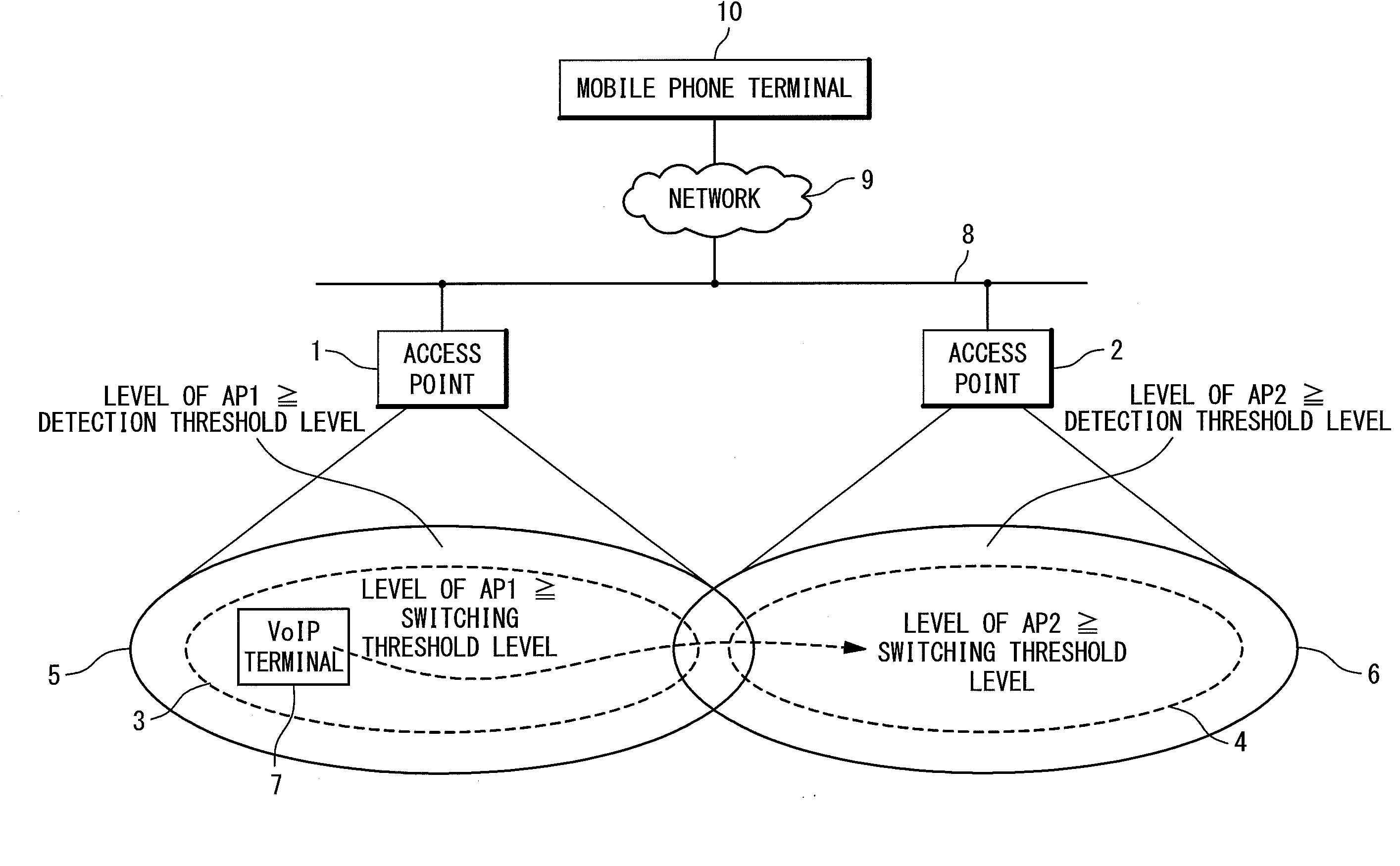
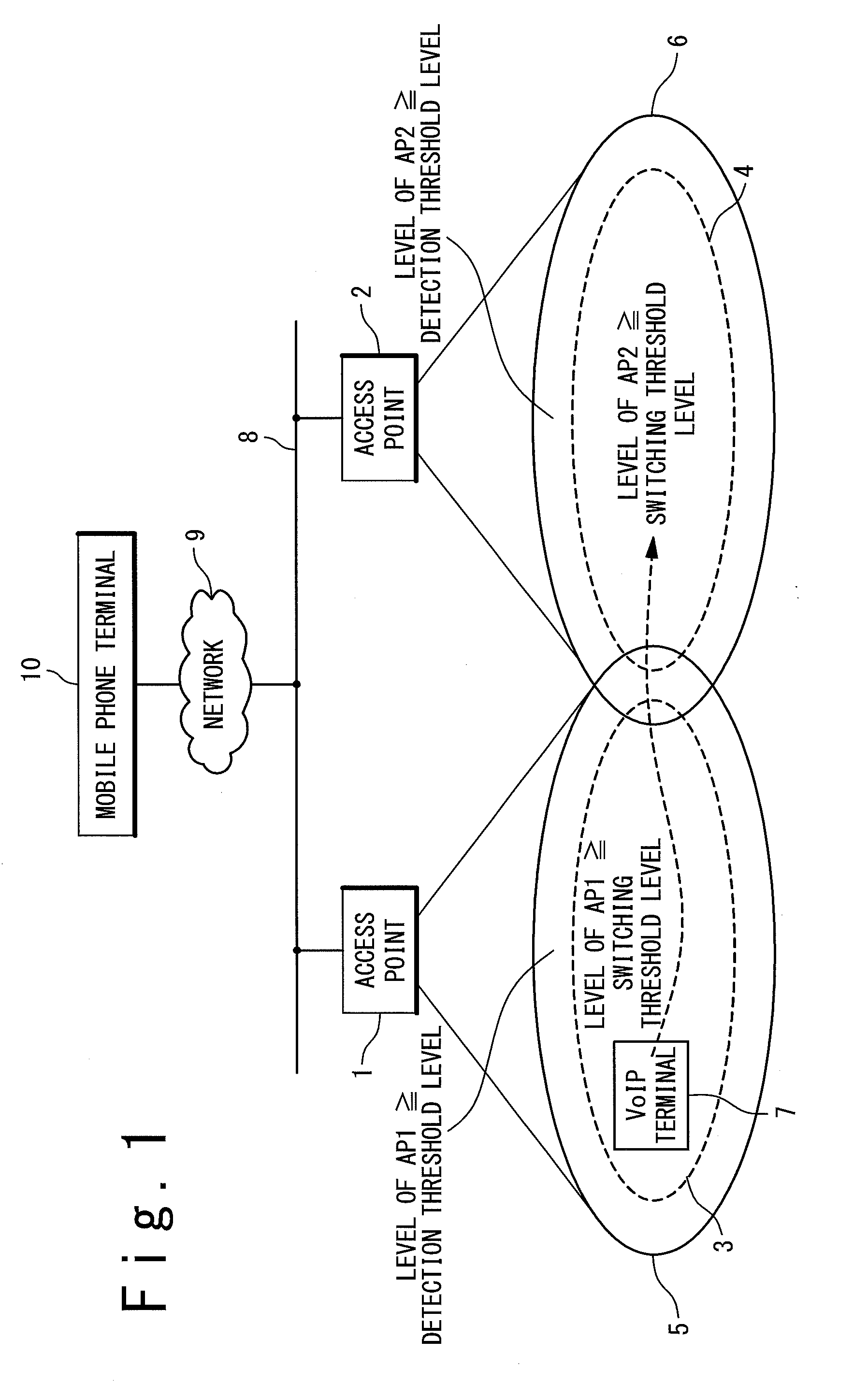
[0026]FIG. 1 is a diagram showing the concept of a wireless LAN network in which handover is carried out. The wireless LAN network includes a first access point 1 (AP1), a second access point 2 (AP2), a first area 3, a second area 4, a third area 5, a fourth area 6, the VoIP terminal 7, a wired network 8, a wide area network 9 and a mobile phone terminal 10.

[0027]The first access point 1 and the second access point 2 are access points based on the specifications of IEEE 802.11. The first area 3 is a area in which the reception electric field intensity of the first access point 1 is equal to or greater than a switching threshold level (the switching threshold level is described in FIG. 3). The second area 4 is an area in which the reception electric field intensity of the second access point 2 is equal to or greater than a switching threshold level. The third area 5 is an area in which the reception electric field intensity of the first access point 1 is equal to or greater than a de...

second exemplary embodiment

[0070]The second exemplary embodiment of the present invention will be described below. It should be noted that the configuration of the VoIP terminal 7 in the second exemplary embodiment is similar to the above-mentioned first exemplary embodiment. Thus, the same description is omitted. The verification scan is useful even in an area in which the reception electric field intensity of the access point in the communication state at present is equal to or greater than the switching threshold.

[0071]FIG. 10A and FIG. 10B are a flowchart showing an operation of the second exemplary embodiment. The second exemplary embodiment is assumed such that an access point as the handover destination candidate is held through a previous all-channels scan.

[0072]At a step S501, the determination of whether or not the background all-channels scan has been carried out for more than seconds indicated by a threshold T3 is carried out. As the result of the determination, if the time indicated by the thresh...

third exemplary embodiment

[0079]The third exemplary embodiment of the present invention will be described below. In the second exemplary embodiment, at the step S509 in FIG. 10B, when the reception electric field intensity from the access point of the handover destination candidate is lower than the switching threshold, the background all-channels scan is carried out. In the third exemplary embodiment, the reception electric field intensity from the access point of the handover destination candidate that is obtained from the verification scan is left as a record. Then, at the step S509 in FIG. 10B, whether or not the reception electric field intensity obtained at this time is equal to or higher than the switching threshold is checked. Moreover, the change from the reception electric field intensity in a previous verification scan is also checked, and is also recorded. For example, the reception electric field intensity obtained in the previous verification scan is defined as a first reception electric field ...


PUM


Abstract

A wireless terminal includes a data transmitting/receiving function and a handover control section. The handover control section scans channels to detect the existence or non-existence of the handover destination candidate on all available wireless channels. The handover control section acquires the handover destination candidate, by scanning the existence or non-existence of the handover destination in advance before handover execution. The verification scan is carried out to check whether or not the candidate is in a communicable area with the terminal. Then, based on the execution result of the verification scan, it performs a handover.

Description

TECHNICAL FIELD[0001]The present invention relates to a wireless terminal and a handover method of a wireless terminal.BACKGROUND ART[0002]In association with the advancement of information communication technology, a wireless LAN has become widely popular. As a technique for properly attaining mobile communication in which the wireless LAN is used, a technique referred to as a handover is known. Japanese Patent Application Publication (JP-P2002-016958A: conventional example 1) describes a technique that uses spreading code corresponding to a base station selected from a base station candidate list, tries the reception of a pilot signal from the base station, and then determines whether or not it is suitable as the base station of a handover destination. Japanese Patent Application Publication (JP-P2004-207922A: conventional example 2) describes a technique in which as a handover processing method used in a wireless LAN system, a wireless terminal apparatus stores data of a wireless...

Claims


Application Information

Patent Timeline
IPC IPC(8): H04W36/00H04W36/36
CPCH04W36/36
Inventor SASHIHARA, TOSHIYUKI
Owner NEC CORP
Why Eureka
Try Eureka