Measurement apparatus and measurement method
a measurement apparatus and measurement method technology, applied in the field of measurement apparatus and measurement method, can solve the problems of inability to precisely evaluate the absorption characteristic and the inability of conventional aot to obtain the absorption characteristi
- Summary
- Abstract
- Description
- Claims
- Application Information
AI Technical Summary
Benefits of technology
Problems solved by technology
Method used
Image
Examples
first embodiment
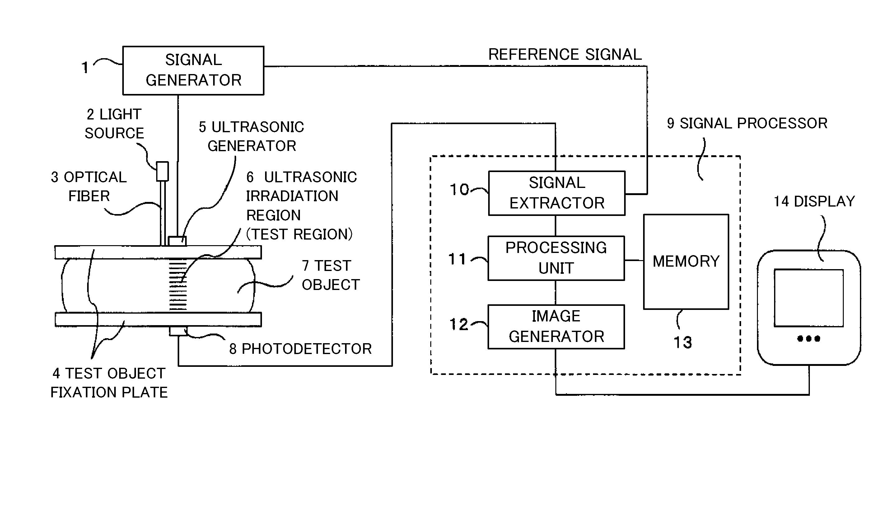
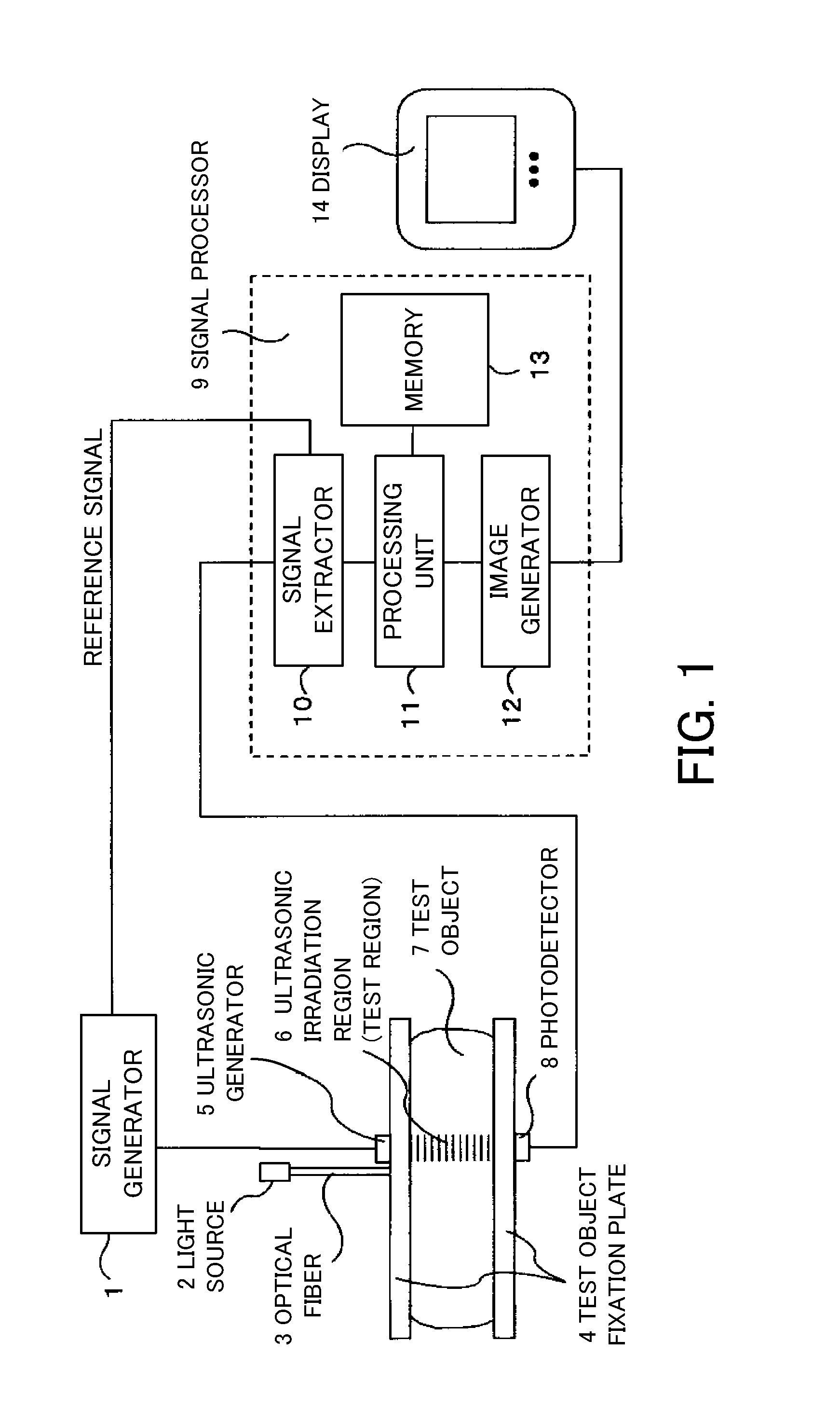
[0027]FIG. 1 is a block diagram of a measurement apparatus according to a first embodiment. The measurement apparatus is configured to measure a spectroscopic characteristic (absorption-scattering characteristic) in a test object using the acousto-optical tomography (“AOT”), and includes a (first) measurement unit, a signal processor 9, and a display 14.
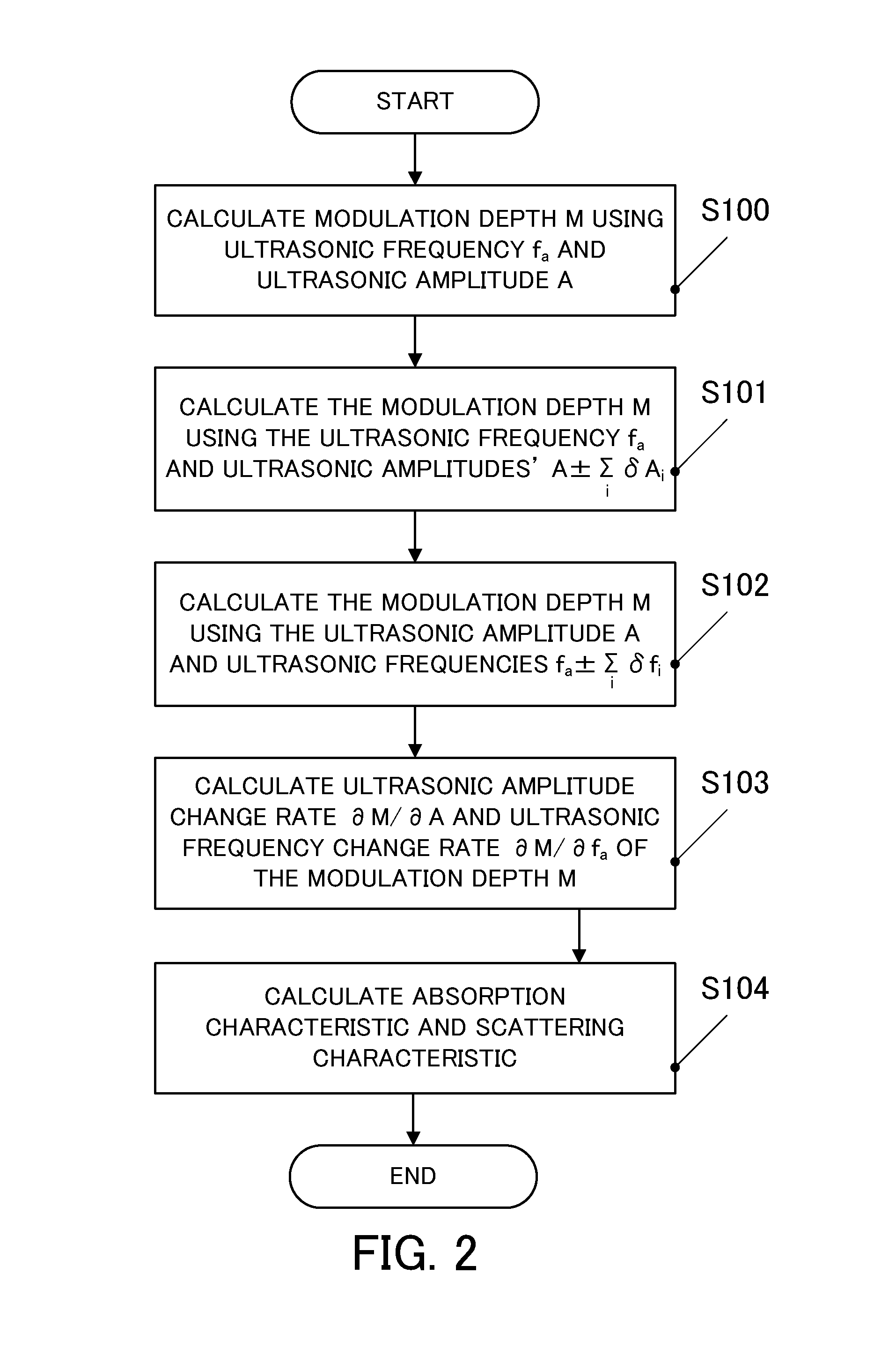
[0028]The (first) measurement unit is configured to irradiate at least three types of ultrasonic waves and light upon a test region 6 in a test object 7. The three types of ultrasonic waves include an ultrasonic wave having a (first) frequency fa and a (first) amplitude “A,” an ultrasonic wave having the frequency fa and a (second) amplitude A1, and an ultrasonic wave having a (second) frequency fa1 and the (first) amplitude “A.” The measurement unit is configured to measure modulated light Ii and non-modulated light I0. The modulated light I1 being modulated by the acousto-optical effect caused by an interaction between the light ir...
second embodiment
[0073]FIG. 4 is a block diagram of a measurement apparatus according to a second embodiment. The signal processor 9 and the display 14 are the same as those of the first embodiment. In this embodiment, the test object 7 is housed in the container 17. A homogeneous medium (matching material) 16 having a known characteristic is filled in a space between the test object 7 and the container 17, and has a refractive index and a scattering coefficient to the light and an acoustic characteristic to the ultrasonic wave equivalent to the test object 7. The ultrasonic generator 5 includes an ultrasonic focus mechanism configured to focus the ultrasonic wave upon an ultrasonic focus region 15 in the test object 7. The ultrasonic focus region 15 is a test region of the AOT.
[0074]FIG. 5 is a lateral sectional view of the container 17 shown in FIG. 4. For simplicity, FIG. 5 shows that the test object 7 spreads over the inside of the container 17 in one section, and a front layer 7a as the outermo...
third embodiment
[0082]Third embodiment calculates the absorption characteristic as well as the scattering characteristic similar to the second embodiment, using the measurement apparatus shown in FIG. 4 which is the same as that of the second embodiment. The measurement apparatus of the third embodiment sequentially scans the position of the ultrasonic focus region 15 in the container 17 for such measurements that the ultrasonic focus regions 15 can three-dimensionally cover the inside of the container 17 entirely. The light incident position of the optical fiber 3 and the detection position of the photodetector 8 are configured to move in accordance with the position of the ultrasonic focus region 15, and both constitute a reflectance measurement system configured to measure the backscattering light similar to the second embodiment. A distance between the optical fiber 3 and the photodetector 8 is made larger as a position of the ultrasonic focus region 15 approaches to the center of the container...
PUM
 Abstract
Description
Claims
Application Information
 - R&D
- Intellectual Property
- Life Sciences
- Materials
- Tech Scout
- Unparalleled Data Quality
- Higher Quality Content
- 60% Fewer Hallucinations
Browse by: Latest US Patents, China's latest patents, Technical Efficacy Thesaurus, Application Domain, Technology Topic, Popular Technical Reports.
© 2025 PatSnap. All rights reserved.Legal|Privacy policy|Modern Slavery Act Transparency Statement|Sitemap|About US| Contact US: help@patsnap.com


