Efficiency monitor for inductive power transmission
- Summary
- Abstract
- Description
- Claims
- Application Information
AI Technical Summary
Benefits of technology
Problems solved by technology
Method used
Image
Examples
first embodiment
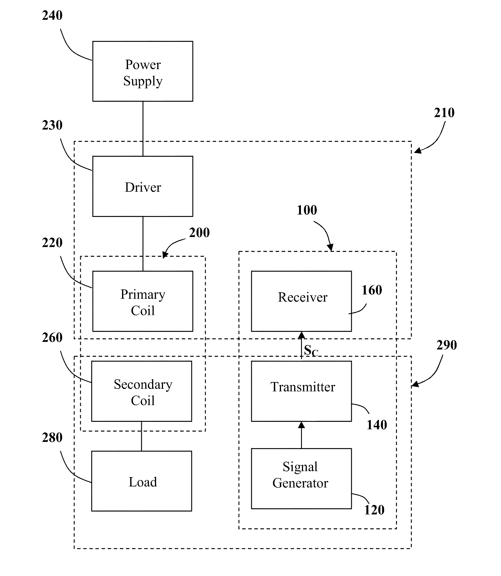
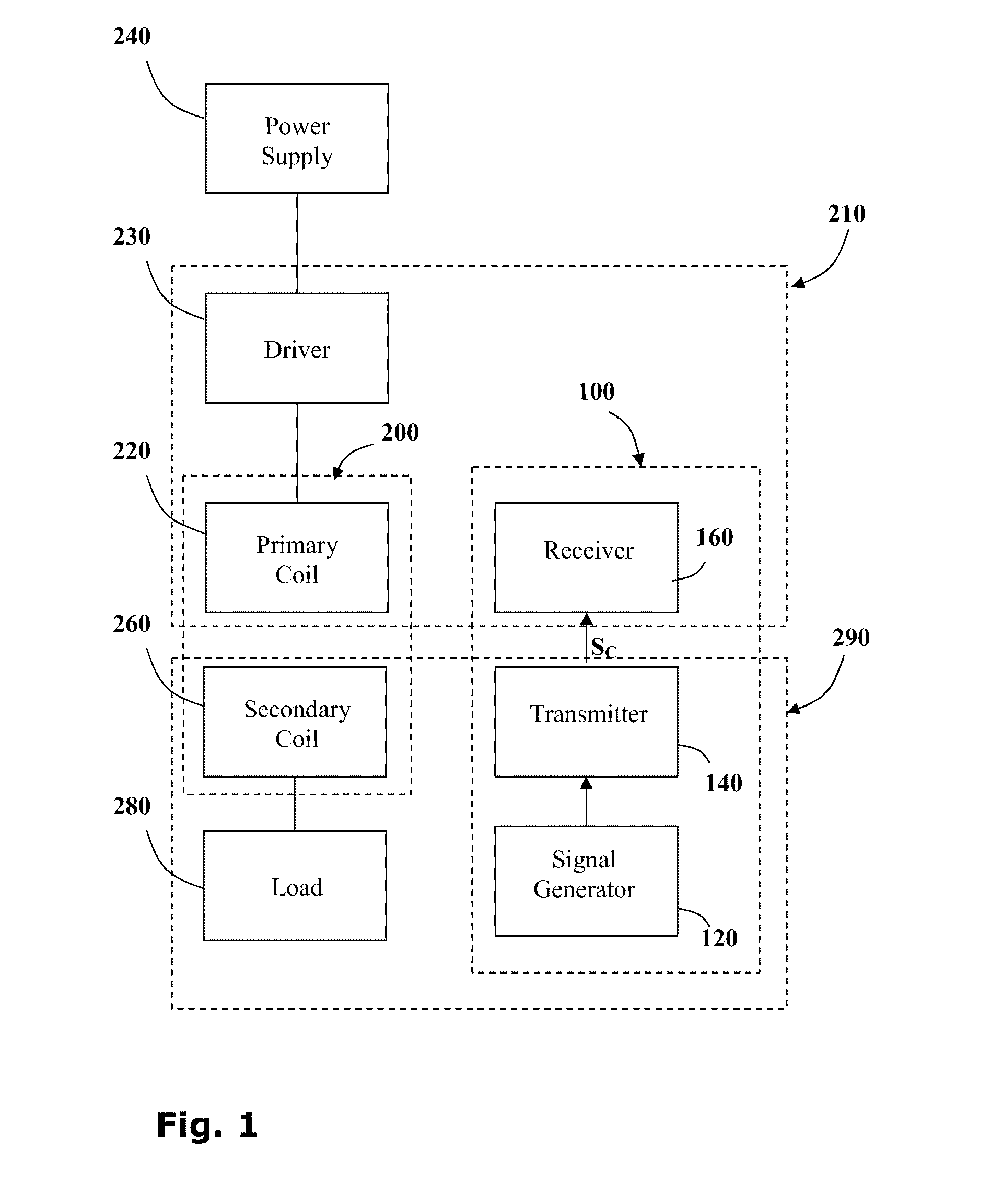
[0093]Reference is now made to FIG. 1 showing a block diagram of the main elements of an inductive power coupling 200 incorporating a signal transfer system 100 according to the invention.
[0094]The inductive power coupling 200 consists of a primary inductive coil 220 and a secondary inductive coil 260. The primary coil 220 is wired to a power supply 240 typically via a driver 230 which provides the electronics necessary to drive the primary coil 220. Driving electronics may include a switching unit providing a high frequency oscillating voltage supply, for example. The secondary coil 260 is wired to an electric load 280.
[0095]When the secondary coil 260 is brought into proximity with the primary coil 220, the pair of coils forms an inductive couple and power is transferred from the primary coil 220 to the secondary coil 260. In this way a power outlet 210 may provide power to an electric device 290.
[0096]The signal transfer system 100 comprises: a signal generator 120, for generatin...
third embodiment
[0130]As an example of the signal transfer system 100 (FIG. 1), with reference to FIG. 3, according to the invention, a signal transfer system 3100 may be integrated into a contactless inductive power coupling system 3200 where power is inductively transmitted from a jack unit 3212 to a plug unit 3292 galvanically isolated therefrom. A transmission circuit 3140 embedded in the plug unit 3292 may be used to transmit control signals SC to a receiver circuit 3160 in the jack 3212. Thus once the primary L1 and secondary L2 coils are aligned, control signals may be passed between the plug 3292 and jack 3212 units with no need to align additional components such as optocouplers, and the like.
[0131]Where a contactless plug 3292 is used, for example to power a portable computer 3290 having on-board power cells 3280, the signal transfer system 3100 may be used to detect the presence of the load 3290 producing a detection signal SDL and then to provide the jack 3212 with signals relating to t...
PUM
 Abstract
Description
Claims
Application Information
 - R&D
- Intellectual Property
- Life Sciences
- Materials
- Tech Scout
- Unparalleled Data Quality
- Higher Quality Content
- 60% Fewer Hallucinations
Browse by: Latest US Patents, China's latest patents, Technical Efficacy Thesaurus, Application Domain, Technology Topic, Popular Technical Reports.
© 2025 PatSnap. All rights reserved.Legal|Privacy policy|Modern Slavery Act Transparency Statement|Sitemap|About US| Contact US: help@patsnap.com


