
Toilet bowl assembly with air aspiration and filtration

a technology of air aspiration and filtration, which is applied in the field of toilet bowl assembly, can solve the problems of insufficient operation of the manual control of the aspiration device, adversely affecting the electric connection, and the installation is therefore subject to failure or maintenance action, and achieves the effect of enhancing the interior tightness

Inactive Publication Date: 2010-03-25
GHARDI RAMEZ +1
View PDF4 Cites 5 Cited by
  • Summary
  • Abstract
  • Description
  • Claims
  • Application Information

AI Technical Summary

Benefits of technology

[0015]Since the electric, electronic and mechanic elements are all grouped in the base and the housing, there is no function-related link between the movement or the position of the seat and the aspirating device. The detection is exclusively effected via the detection window situated in the front of the housing above the seat. This detection allows the function of the assembly to be managed by the control circuit in order to guarantee the long-term operational reliability without exhausting the supply formed by batteries in the most simple and most practical case of installation of the assembly.
[0055]The infrared detector is a very efficient solution that consumes little current and therefore guarantees the longevity of the battery power supply.

Problems solved by technology

However, the toilet bowl lid proposed in this document has the drawback of controlling the function of the aspirating device through a switch that is operated either manually or automatically under the weight of a user, and therefore the bowl is provided with a detector.
The manual control has the drawbacks of all manual controls, all with respect to the installation, the maintenance and the use; the manual control has to be mounted at a position within reach.
Due to these different drawbacks, the functioning of the manually controlled aspirating device is not satisfactory.
The detector mounted to the seat and reacting under the weight of the user on the seat, has the drawback that requires a detector under the seat and a connection between the detector and the control circuit in a housing of the stationary part.
The pivoting movement of the seat being lifted will necessarily adversely affect the electric connection that therefore has to be replaced from time to time.
This installation is therefore subject to failures or requires maintenance action from time to time.

Method used


Image

  • Toilet bowl assembly with air aspiration and filtration
  • Toilet bowl assembly with air aspiration and filtration
  • Toilet bowl assembly with air aspiration and filtration

Examples


Embodiment Construction

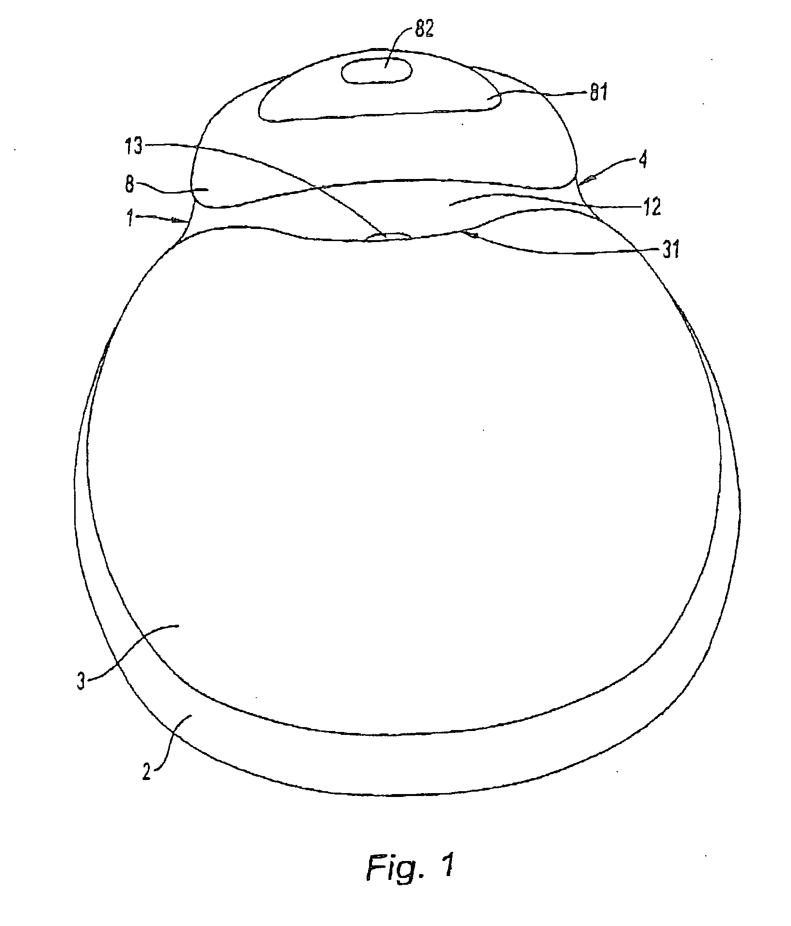
[0070]According to FIG. 1, the disclosure refers to a toilet bowl assembly formed by a base 1 fixed to the non-illustrated bowl and bearing a hinged seat 2 covered by a lid 3 also hinged, as well as an aspirating device situated in the housing 4 of the base.

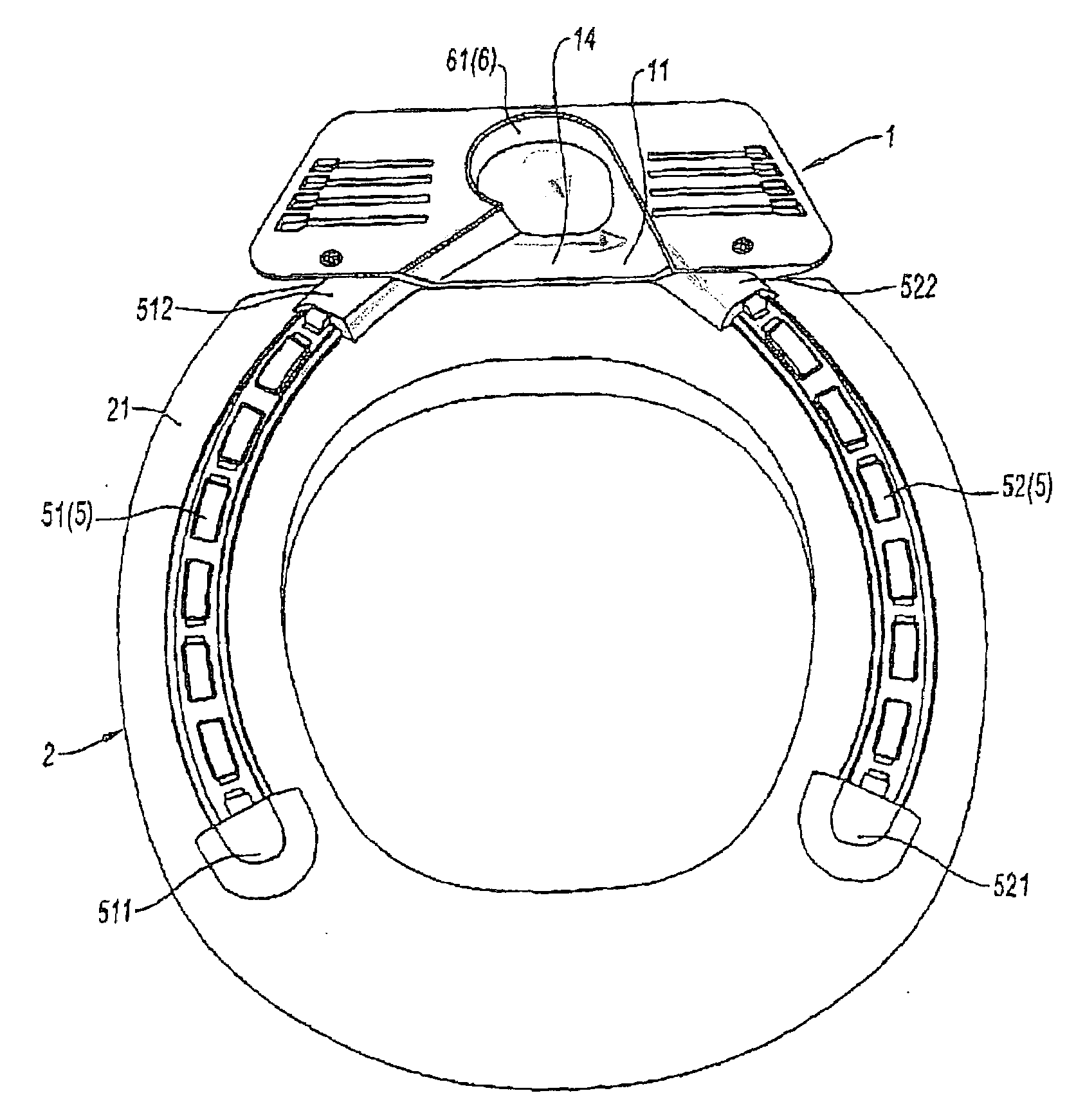
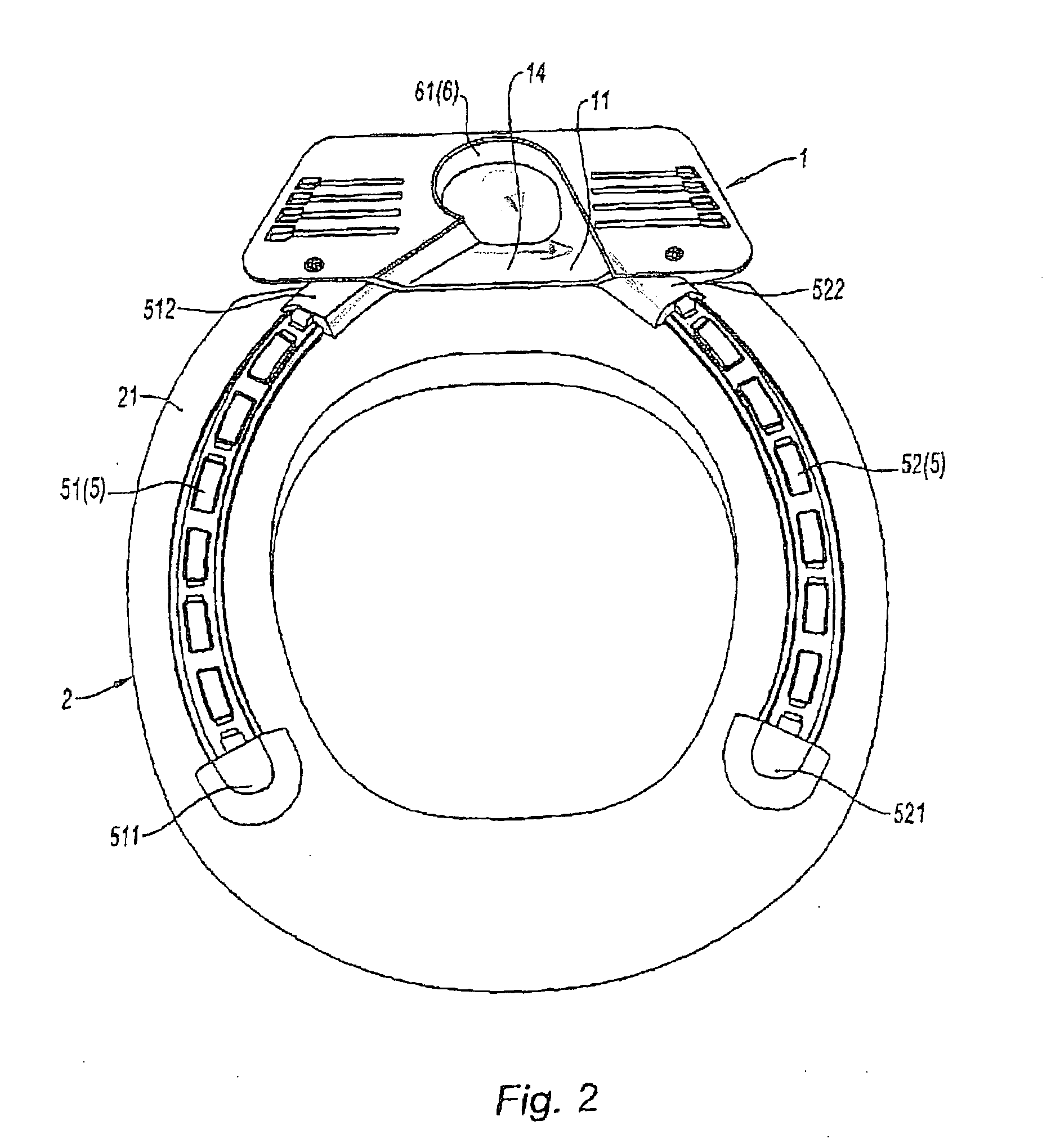
[0071]The lower side 21 of the seat 2 (FIG. 2) is provided with a seal 5 with two branches 51, 52, open to the front and the rear to allow the passage of air from the outside and across the bowl towards an aspiration opening 11 formed in the base 1 and ending in the aspirating device 6 formed by a rotor 61 provided with an electric motor that draws air and conveys it across a filter 62 ending outside the housing 4.

[0072]The operation of the assembly is controlled by a control circuit situated in the extension 12 of the base 1. This circuit controls the operation of the aspirating device 6 as a function of the presence detected by the presence detector, in particular an infrared presence detector, the timing of the operation, as w...


PUM


Abstract

A toilet bowl assembly comprising a base fixed to a bowl, provided with a toilet seat and a device for aspirating air from the bowl. The base comprises an extension that has its upper part provided with a presence detection window directed to above the seat and forming an aspiration channel opening into the bowl. A circuit for controlling the function of the aspirating device with an infrared detector situated in the detection window to detect a presence on the seat and with an electric power supply for the circuit and the aspirating device.

Description

BACKGROUND[0001]1. Field of the Disclosure[0002]The present disclosure relates to a toilet bowl assembly comprising a base fixed to the bowl, provided with a toilet seat and a device for aspirating air from the bowl, the underside of the seat being provided with a seal by which the seat is supported on the rim of the bowl, said seal being open to the front and to the rear to allow air to pass towards the aspirator through aspiration opening formed in the base, the aspirating device comprising a rotor driven by an electric motor to aspirate air and circulate it through a filter that discharges from the housing.[0003]2. Discussion of the Background Art[0004]Such an assembly is already known from the document EP 0 934 720, for instance. However, the toilet bowl lid proposed in this document has the drawback of controlling the function of the aspirating device through a switch that is operated either manually or automatically under the weight of a user, and therefore the bowl is provide...

Claims


Application Information

Patent Timeline
IPC IPC(8): E03D9/04
CPCE03D9/052A47K13/307
Inventor GHARDI, RAMEZGHADRI, JAYDA
Owner GHARDI RAMEZ
Learn More