
Fuel reforming process for internal combustion engines

a technology for internal combustion engines and fuel reforming, which is applied in the direction of combustible gas chemical modification, combustion air/fuel air treatment, combustion-air/fuel-air treatment, etc. it can solve the problems of not reducing greenhouse pollutants, water application, and device drawbacks, so as to increase the efficiency of the world's remaining fossil fuels. , the effect of increasing the combustive power

Inactive Publication Date: 2010-03-25
PENMAN ROBERT R
View PDF3 Cites 7 Cited by
  • Summary
  • Abstract
  • Description
  • Claims
  • Application Information

AI Technical Summary

Problems solved by technology

Although exhaust catalytic converters remove noxious gases and reduce some green house gases, these devices suffer from several drawbacks.
Further, the conversion of gases within these devices does not reduce greenhouse pollutants at an efficient rate.
This process as applied to water, however, will require more experimentation and would require higher temperatures for dissociation than petroleum products and ethanol.

Method used


Image

  • Fuel reforming process for internal combustion engines
  • Fuel reforming process for internal combustion engines
  • Fuel reforming process for internal combustion engines

Examples


Embodiment Construction

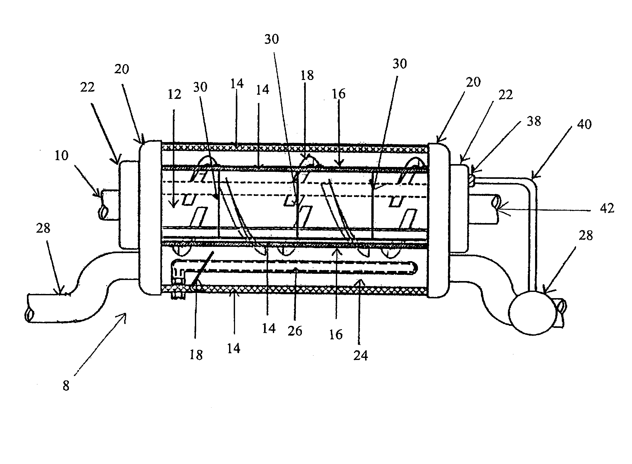
[0025]The present invention is directed towards a fuel reforming device for internal combustion engines, which are discussed in terms of internal combustion engines, and more particularly, to a fuel reforming process that increases fuel efficiency and reduces green house gas pollutants. The following discussion includes a description of the fuel reforming process, system, and device for internal combustion engines. Reference will now be made in detail to exemplary embodiments of the disclosure, which are illustrated in the accompanying figures.

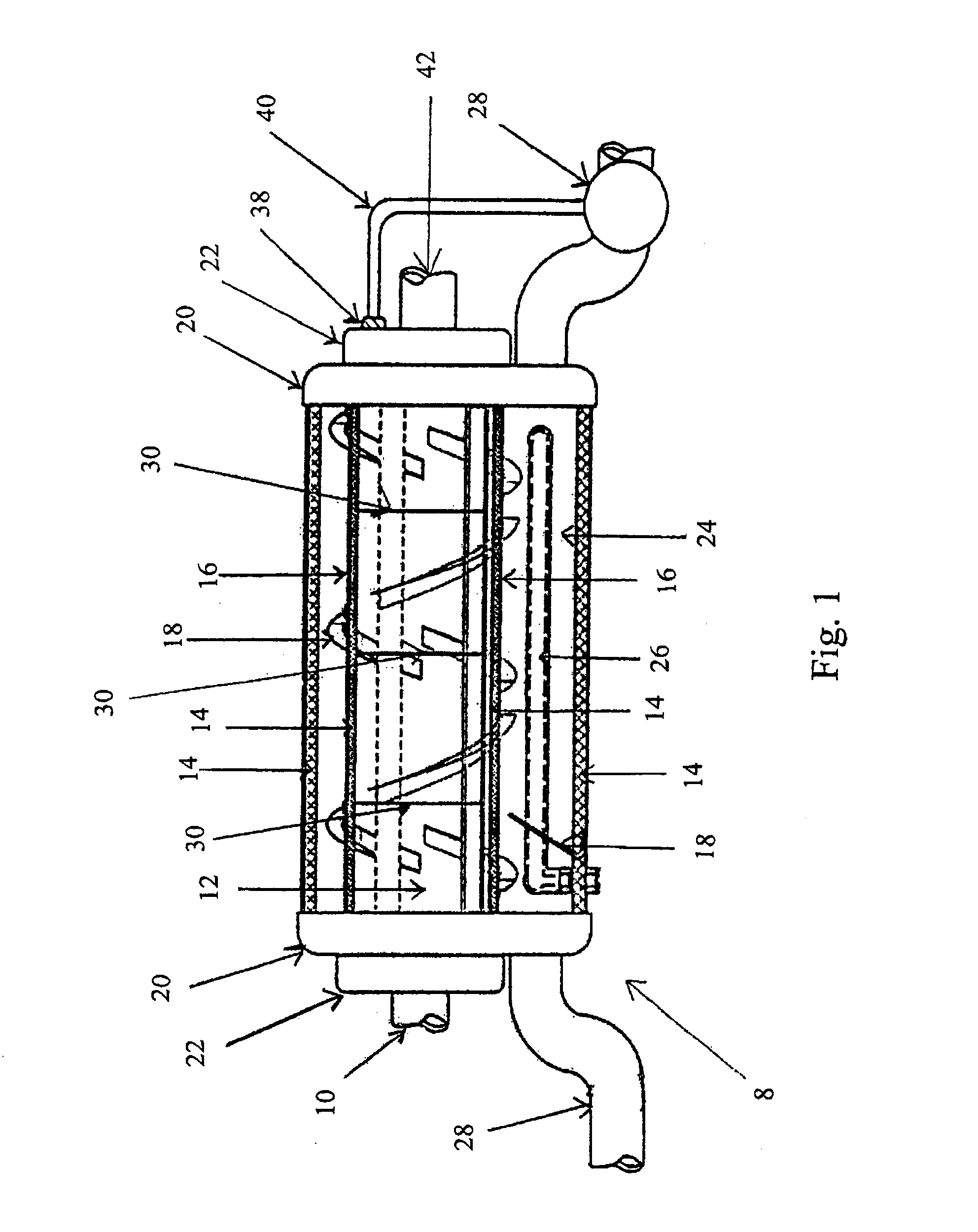
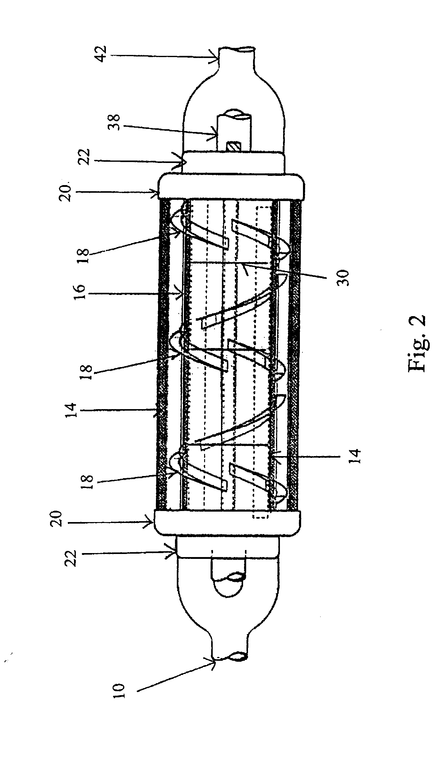
[0026]Referring to FIG. 1, a fuel reforming device 8 is designed to convert a liquid fuel that is passed from a fuel filter into a gaseous fuel prior to entering an engine's fuel injectors. The present disclosure is significantly smaller in size and is contained in comparison to prior art. The fuel reforming device 8 is installed onto injectors (not shown in the figures) to perform this process.

[0027]Referring to FIGS. 1-2, the liquid fuel exi...


PUM

PropertyMeasurementUnit
temperatureaaaaaaaaaa
catalytic temperatureaaaaaaaaaa

Abstract

A fuel reforming system, process, and device including a catalytic chamber and a heating chamber. The catalytic chamber, further including a fluid fuel intake and a gaseous fluid exit port and at least one heat exchanger for distributing heat between the heating chamber and the catalytic chamber. The catalytic chamber further including a screen member having a surface, wherein the member includes a catalytic deposit made from a combination of platinum and rhodium alloy. A catalytic conversion of converting liquid fuel to gaseous fuel occurs within the catalytic chamber. Fuel exits the fuel reforming device through a gaseous fluid exit port.

Description

CROSS-REFERENCE TO RELATED APPLICATIONS[0001]This application is a divisional application of U.S. application Ser. No. 12 / 015,253 filed in the U.S. Patent and Trademark Office on Jan. 16, 2008 by Penman, which claims the benefit of U.S. Provisional Application No. 60 / 982,204, filed on Oct. 24, 2007 by Penman, the entire contents of each are incorporated herein in their entirety.BACKGROUND[0002]1. Technical Field[0003]The present invention generally relates to internal combustion engines, and more particularly, to a fuel reforming process that improves the efficiency of fuel consumption and reduces environmental pollutants generated by internal combustion engines.[0004]2. Background of the Invention[0005]In response to tightening EPA regulations on automobile exhaust, catalytic converters were introduced to the United States market in the 1970s. Catalytic converters are universally employed in automobile exhaust systems for the reduction of carbon monoxide, hydrocarbons, and oxides o...

Claims


Application Information

Patent Timeline
Patent Type & Authority Applications(United States)
IPC IPC(8): C10J1/20
CPCF02B43/04F02B51/02F02M25/12Y02T10/32F02M31/18Y02T10/126F02M27/02Y02T10/12Y02T10/30
Inventor PENMAN, ROBERT R.
Owner PENMAN ROBERT R
Learn More