Loading auger deflector

a technology of deflector and loader, which is applied in the direction of transportation items, loading/unloading vehicle arrangment, thresher, etc., can solve the problem of premature wear and tear of the loading auger fligh

Inactive Publication Date: 2010-03-25
DEERE & CO
View PDF13 Cites 7 Cited by
  • Summary
  • Abstract
  • Description
  • Claims
  • Application Information

AI Technical Summary

Benefits of technology

[0007]The invention in another form is directed to a harvesting machine for gathering grain from a field, processing the gathered grain and temporarily storing the grain for subsequent transfer to a larger capacity container. The harvesting machine includes a grain storage tank and an auger conveyor with a hollow generally cylindrical tube and a coaxially disposed auger journalled for rotation within the hollow tube to convey grain from a first tube end to a second tube end for discharge into the storage tank. There is a grain deflector fixed to the second tube end having a grain flow diverting plate spaced from the second tube end which is selectively movable between a first position where grain flow is angularly diverted from vertical in a first direction and a second position where grain flow is angularly diverted from vertical in a second direction. The diverting plate is pivotably supported for limited motion about an axis extending transverse to the tube axis. The deflector also has a flange located to one side of the second tube end for confining grain flow to the storage tank which is primarily effective to confine grain flow while the grain level in the tank is below the second tube end.

Problems solved by technology

Also, the flighting of the loading auger wears out prematurely due to the excessive grain above the loading auger.

Method used


Image

  • Loading auger deflector
  • Loading auger deflector
  • Loading auger deflector

Examples


Embodiment Construction

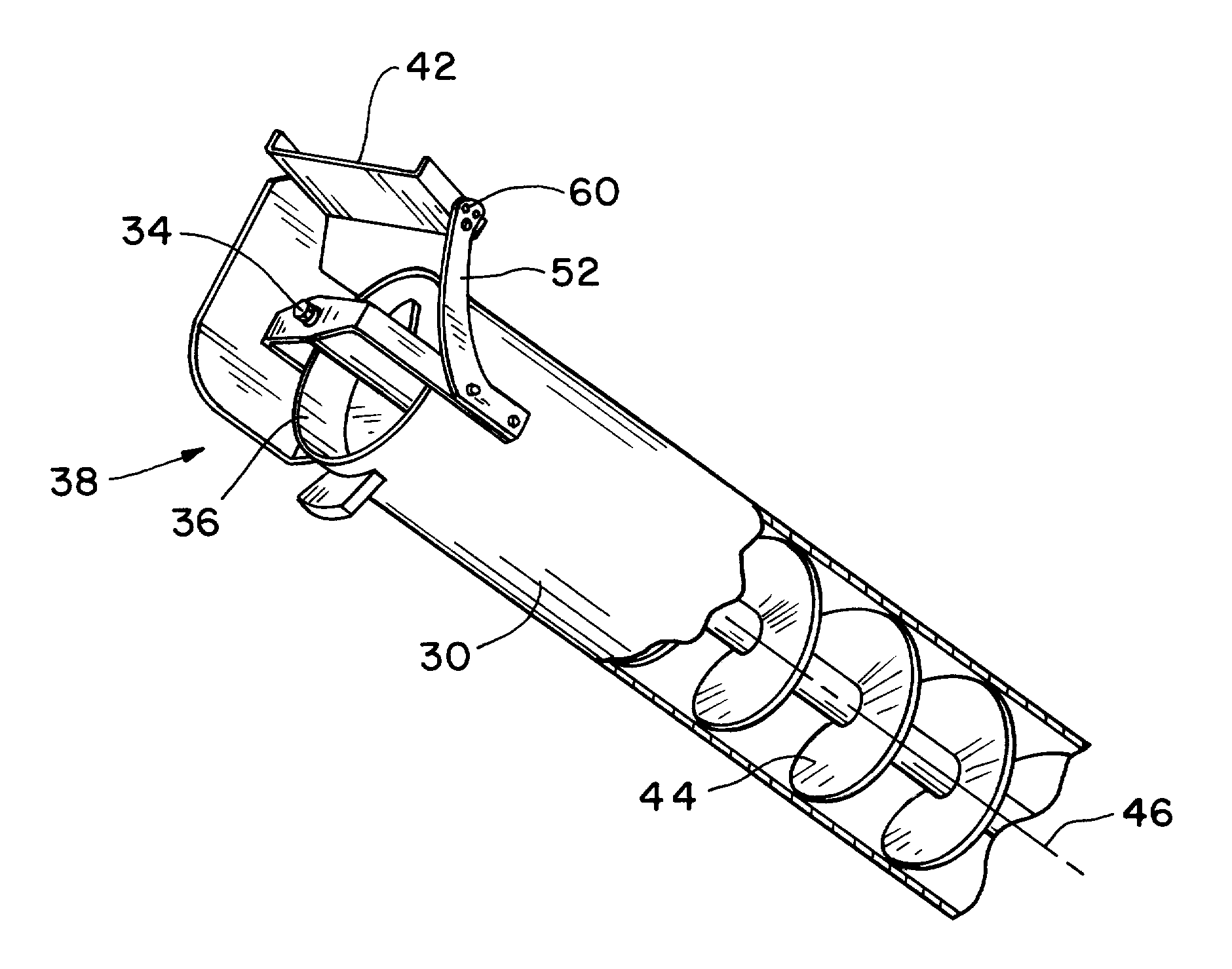
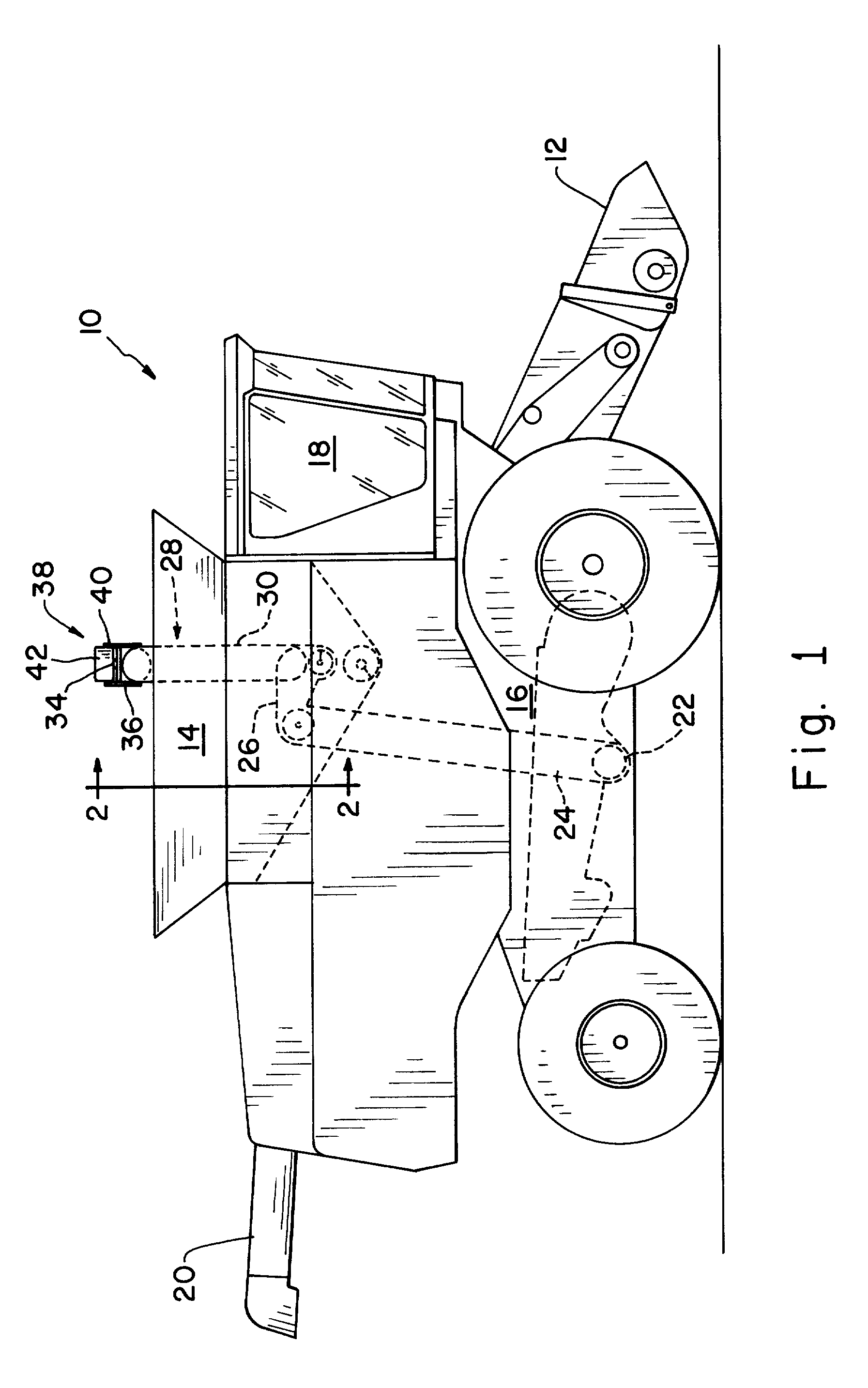
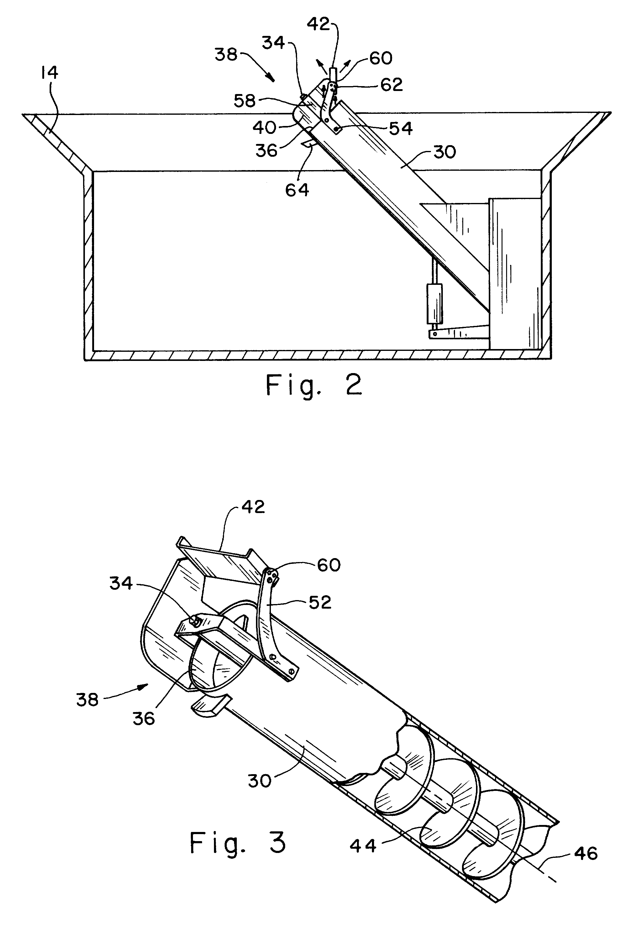
[0014]Referring now to FIG. 1, there is schematically shown an agricultural work machine 10 in accordance with an embodiment of the present invention. In the present embodiment, agricultural harvesting machine 10 is in the form of a self-powered combine including a supporting structure 16 having wheels supporting a frame. It will be understood that the present invention is applicable to other types of agricultural harvesting machines, self-powered or otherwise.

[0015]Combine 10 may include a header (not shown) attached to a feeder house 12, a hopper or grain tank 14 which functions as a temporary on-board storage location, a hopper unloading system indicated generally at 20, and a cab 18 for housing the operator of the harvesting machine. The header may be configured in known manner to cut the crop being harvested, which is then transferred to threshing, separating and cleaning assemblies (not shown) that separate the agricultural product, e.g., grain, from the chaff. Chaff may exit ...


PUM


Abstract

A clean grain conveyor system for a harvesting machine having grain gathering, cleaning and temporary storage capabilities includes a clean grain elevator mechanism, a grain storage tank and a loading auger conveyor for moving grain from the elevator mechanism to a discharge end at the storage tank. The conveyor includes a hollow generally cylindrical tube extending obliquely upwardly from the elevator to the grain storage tank and a coaxially disposed auger journalled for rotation within the hollow tube. A grain flow deflector is fixed to the tube discharge end for minimizing grain scattering outside the tank and for selectively directing the flow of grain from the tube discharge end to compensate for different crops and crop conditions, and to generally center the pile of accumulated grain within the tank.

Description

FIELD OF THE INVENTION[0001]The present invention relates to agricultural harvesting machinery and more particularly to a system for conveying crop to a combine grain storage tank.BACKGROUND OF THE INVENTION[0002]Agricultural harvesting machines, such as combines, are employed in the agricultural industry for various tasks, including harvesting crops. During harvesting operations, typical such agricultural harvesting machines move through a crop field while operating a header at the front of the harvesting machine to cut the crop. The header cuts and then moves the cut crop into a feeder house and the feeder house transports crop into threshing, separating and cleaning areas of the combine where crop is removed from the non-grain crop materials and then transferred to the harvesting machine's hopper such as a grain tank for temporary storage. When the hopper is full, the combine moves to a transport vehicle such as a large truck or trailer to discharge the load and then resume harve...

Claims


Application Information

Patent Timeline
Patent Type & Authority Applications(United States)
IPC IPC(8): A01D41/12B60P1/40A01F12/46
CPCA01D41/1208
Inventor TEMPLE, DOUGLAS G.TANK, BRIAN J.
Owner DEERE & CO
Why Eureka
Try Eureka