Diaphragm

a diaphragm and support technology, applied in the field of diaphragms, can solve the problems of spoons being buried in foodstuffs, and achieve the effects of increasing weight and cost savings, and reducing the thickness and weight of the reinforcing suppor

Inactive Publication Date: 2010-03-25
CROWN PACKAGING TECH
View PDF58 Cites 12 Cited by
  • Summary
  • Abstract
  • Description
  • Claims
  • Application Information

AI Technical Summary

Benefits of technology

[0040]Providing the annulus with a hollow cross-section helps to minimise the thickness and weight of the reinforcing support compared to merely forming the reinforcing support as a homogenous solid entity. The hollow cross-section may extend about all or part of the annulus; maximising the circumferential extent of the hollow cross-section will increase the weight and cost savings. The weight and cost savings of a hollow annulus will be particularly noticeable when making the reinforcing support for a diaphragm having one or more inclined areas, because it would:
[0041]Locating the removable tamper evident band above the recess results in the recess being closed and thereby avoids unwanted matter (such as dirt) collecting in the recess, whilst also providing assurance to an end-consumer that a container incorporating the reinforcing support has not been tampered with. Providing a generally planar surface enables easy stacking of containers incorporating the reinforcing support. The tamper evident band may incorporate a tear-off strip.
[0042]In a further embodiment, the reinforcing support is adapted to be releasably attachable to a container comprising the diaphragm of the present invention so as to provide a reusable seal between the inside and outside of the container. This aspect of the present invention enables a seal to be maintained between the contents of the container and the environment outside of the container even after the diaphragm has been removed. Maintaining such a seal may be particularly advantageous when considering containers for storing perishable products, such as foodstuffs. Further, it may also avoid the need for a secondary closure in order to retain the reinforcing support in position. Conveniently, the reusable seal may be provided by a snap-fit connection between all or part of the periphery of the reinforcing support and the diaphragm / container. In these situations, the reinforcing support would, in use, be performing the following roles:
[0043]a) resisting distortion of the diaphragm of the present invention when the container is subjected to a pressure differential;

Problems solved by technology

However, by the time the filled container reaches an end-consumer, settlement of the foodstuff which is stored in the container may well cause the spoon to become buried in the foodstuff.

Method used


Image

  • Diaphragm
  • Diaphragm
  • Diaphragm

Examples


Embodiment Construction

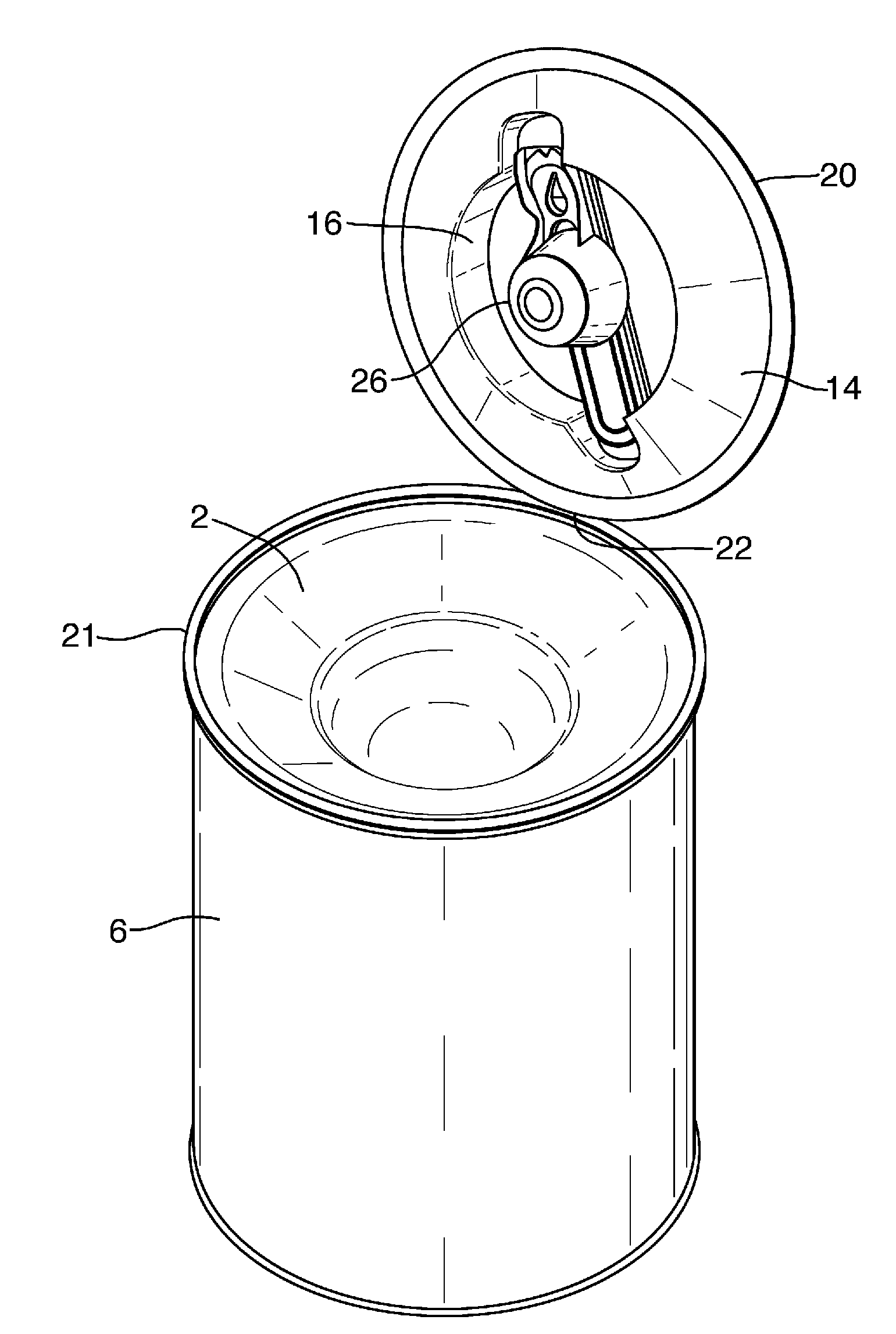
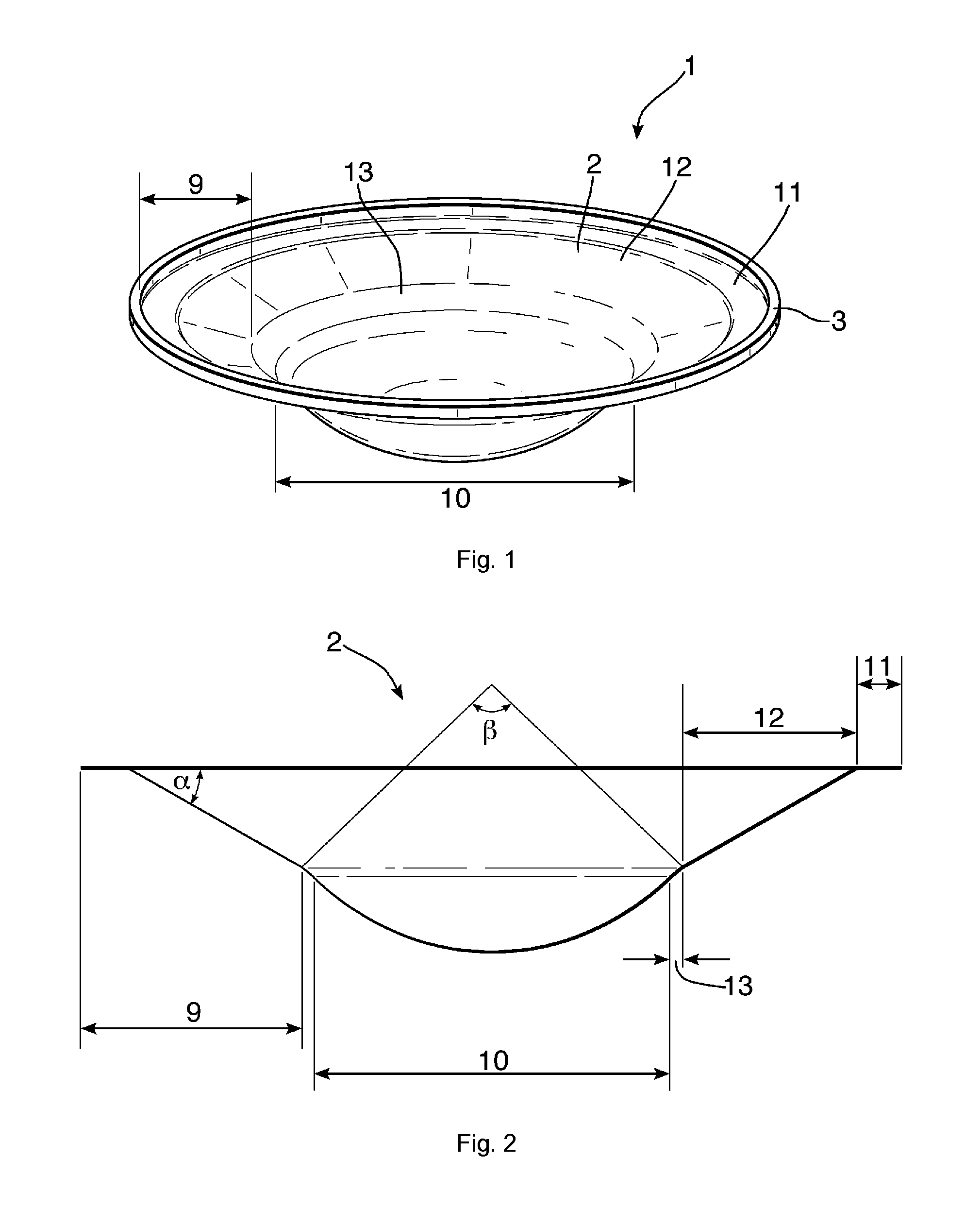
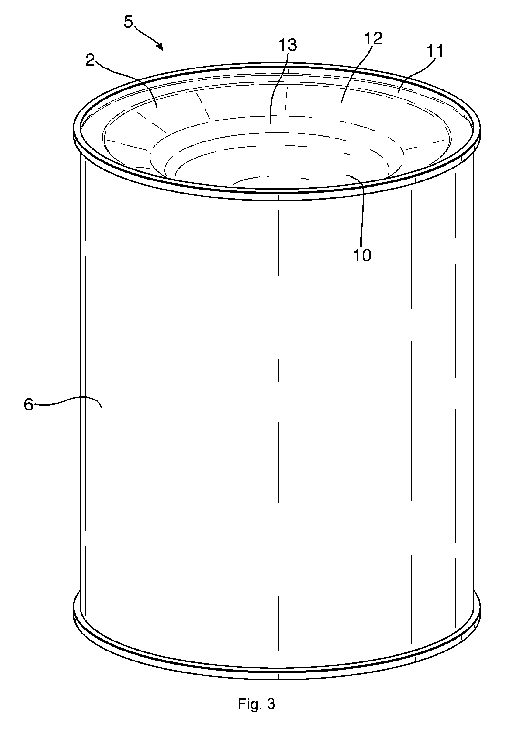
[0069]As shown in FIGS. 1, 3 and 4, a closure 1 is formed by a diaphragm 2 sealed to an annular metal ring 3 along a sealing surface 4. The closure 1 is seamed onto an access opening 5 of a metal can body 6 by the use of a double seam 7 (see FIG. 4). The sealing surface 4 is approximately perpendicular to the longitudinal axis 8 of the can body 6 (see FIG. 4).

[0070]As shown in FIGS. 1 and 2, the diaphragm 2 has an annular region 9 which surrounds a shaped cavity 10. The annular region 9 consists of a flat annular area 11 located at the periphery of the diaphragm 2 and an inclined area 12 situated inwardly of the annular area 11. The diaphragm 2 is provided with a radius of curvature of approximately 5 millimetres at the transition 13 between the annular region 9 and the cavity 10. The transition 13 defines the periphery of the cavity 10, i.e. the point from which the cavity depth is measured. The cavity 10 is generally part-spherical in shape.

[0071]As shown in FIG. 2, the inclined a...


PUM


Abstract

A first aspect of the present invention relates to a diaphragm (2) for sealing an access opening (5) of a container body (6), the diaphragm being semi-rigid and formed with a shaped cavity (10). The present invention is particularly (but not exclusively) suitable for use with metal cans for packaging foodstuffs. A second aspect of the present invention relates to a reinforcing support (14) for locating over the diaphragm when used to seal an access opening of a container body. A third aspect of the present invention relates to a spoon (26) suitable for use with a container comprising the diaphragm.

Description

TECHNICAL FIELD[0001]A first aspect of the present invention relates to a diaphragm for sealing an access opening of a container body, the diaphragm being semi-rigid and provided with a shaped cavity. The present invention is particularly (but not exclusively) suitable for use with metal cans for packaging foodstuffs. A second aspect of the present invention relates to a reinforcing support for locating over the diaphragm when used to seal an access opening of a container body. A third aspect of the present invention relates to a spoon suitable for use with a container comprising the diaphragm.BACKGROUND ART[0002]Containers for the packaging of non-liquid foodstuffs, such as milk powder, are known. Such a known container comprises a container body of generally circular cross-section, the container body having a sidewall and a base. The end of the container body opposite the base defines an access opening through which the foodstuff may be dispensed from the container. A closure—in t...

Claims


Application Information

Patent Timeline
Patent Type & Authority Applications(United States)
IPC IPC(8): B65D51/18B65D53/00A47J43/28
CPCB65D51/247B65D2251/0093B65D2251/0028
Inventor STUART, IAIN CHARLES EDWARD
Owner CROWN PACKAGING TECH
Why Eureka
Try Eureka