Regenerative shock absorber system

a technology of shock absorber and shock absorber, which is applied in the direction of machine/engine, transportation and packaging, jet propulsion mounting, etc., can solve the problem of wasting a significant amount of energy as hea

a technology of shock absorber and shock absorber, which is applied in the direction of machine/engine, transportation and packaging, jet propulsion mounting, etc., can solve the problem of wasting a significant amount of energy as hea

US20100072760A1Active Publication Date: 2010-03-25CLEARMOTION INC

Image

  • Regenerative shock absorber system
  • Regenerative shock absorber system
  • Regenerative shock absorber system

Examples


Embodiment Construction

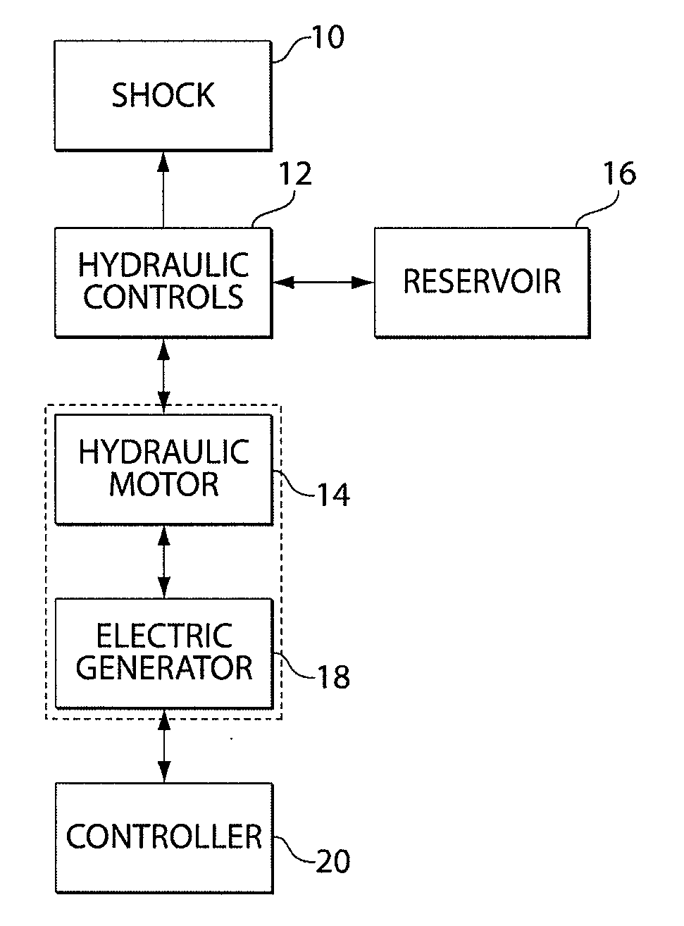
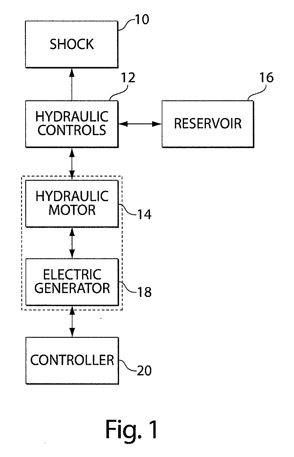
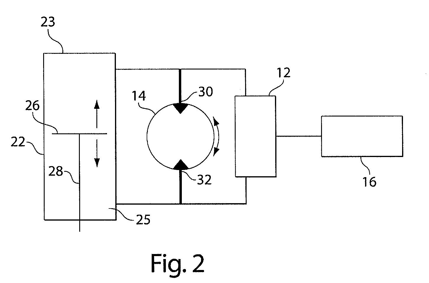
[0026]Aspects of the system relate to a regenerative shock absorber. Embodiments of the shock absorber may include a housing and a piston that moves at least partially through a compression stroke when the shock is compressed. The piston may additionally move at least partially through an extension stroke when the shock is extended (i.e., the piston may be double-acting). When the piston moves, hydraulic fluid is pressurized and moved to drive a hydraulic motor. The hydraulic motor, in turn, drives an electric generator that produces electric energy that may be provided to a vehicle.

[0027]According to one aspect, movement of the piston through the housing may always be associated with corresponding movement of the hydraulic motor. That is, fluid connections between the shock absorber and the hydraulic motor may be configured such that pressure of hydraulic fluid that is associated with movement of the piston through the compression volume always urges the hydraulic motor to move in ...


PUM


Abstract

A regenerative shock absorber that include a housing and a piston that moves at least partially through the housing when the shock is compressed or extended from a rest position. When the piston moves, hydraulic fluid is pressurized and drives a hydraulic motor. The hydraulic motor, in turn, drives an electric generator that produced electric energy. The electric energy may be provided to a vehicle, among other things. The regenerative shock absorber may also provide ride performance that comparable to or exceeds that of conventional shock absorbers.

Description

RELATED APPLICATIONS[0001]This application is a continuation-in-part of and claims priority to U.S. application Ser. No. 12 / 104,800, filed Apr. 15, 2008, which is hereby incorporated by reference in its entirety.BACKGROUND[0002]1. Field of Invention[0003]Aspects of the invention relate to shock absorber systems and more particularly to shock absorber systems that capture energy associated[0004]1. Field of Invention[0005]Aspects of the invention relate to shock absorber systems and more particularly to shock absorber systems that capture energy associated with relative motion.[0006]2. Discussion of Related Art[0007]A typical automobile suspension system includes a shock absorber that dissipates energy associated with suspension motion. Shock absorbers typically include a shock housing with a piston positioned inside that is movable in both a compression stroke and an extension stroke. An orifice is positioned in the piston. The motion of the piston causes a high viscosity fluid to pa...

Claims


Application Information

Patent Timeline
25 Mar 2010
Publication
US20100072760A1
IPC
H02K7/18; B60G11/00
CPC
B60G13/14; H02K7/1876; B60G2202/24; B60G2202/416; B60G2202/42; B60G2204/62; B60G2206/41; B60G2300/60
Inventors
ANDERSON, ZACKARY; JACKOWSKI, ZACHARY