Dual drive electromechanical actuator with center output

Inactive Publication Date: 2010-03-25
HONEYWELL INT INC
View PDF14 Cites 6 Cited by
  • Summary
  • Abstract
  • Description
  • Claims
  • Application Information

AI Technical Summary

Benefits of technology

[0009]Furthermore, other desirable features and characteristics of the actuator and actuation control system will become apparent from

Problems solved by technology

Although these known EMAs are generally useful, the complex mechanical linkage can adversely impact overall system weight, size, and cost.

Method used


Image

  • Dual drive electromechanical actuator with center output
  • Dual drive electromechanical actuator with center output
  • Dual drive electromechanical actuator with center output

Examples


Embodiment Construction

[0016]The following detailed description is merely exemplary in nature and is not intended to limit the invention or the application and uses of the invention. Furthermore, there is no intention to be bound by any theory presented in the preceding background or the following detailed description.

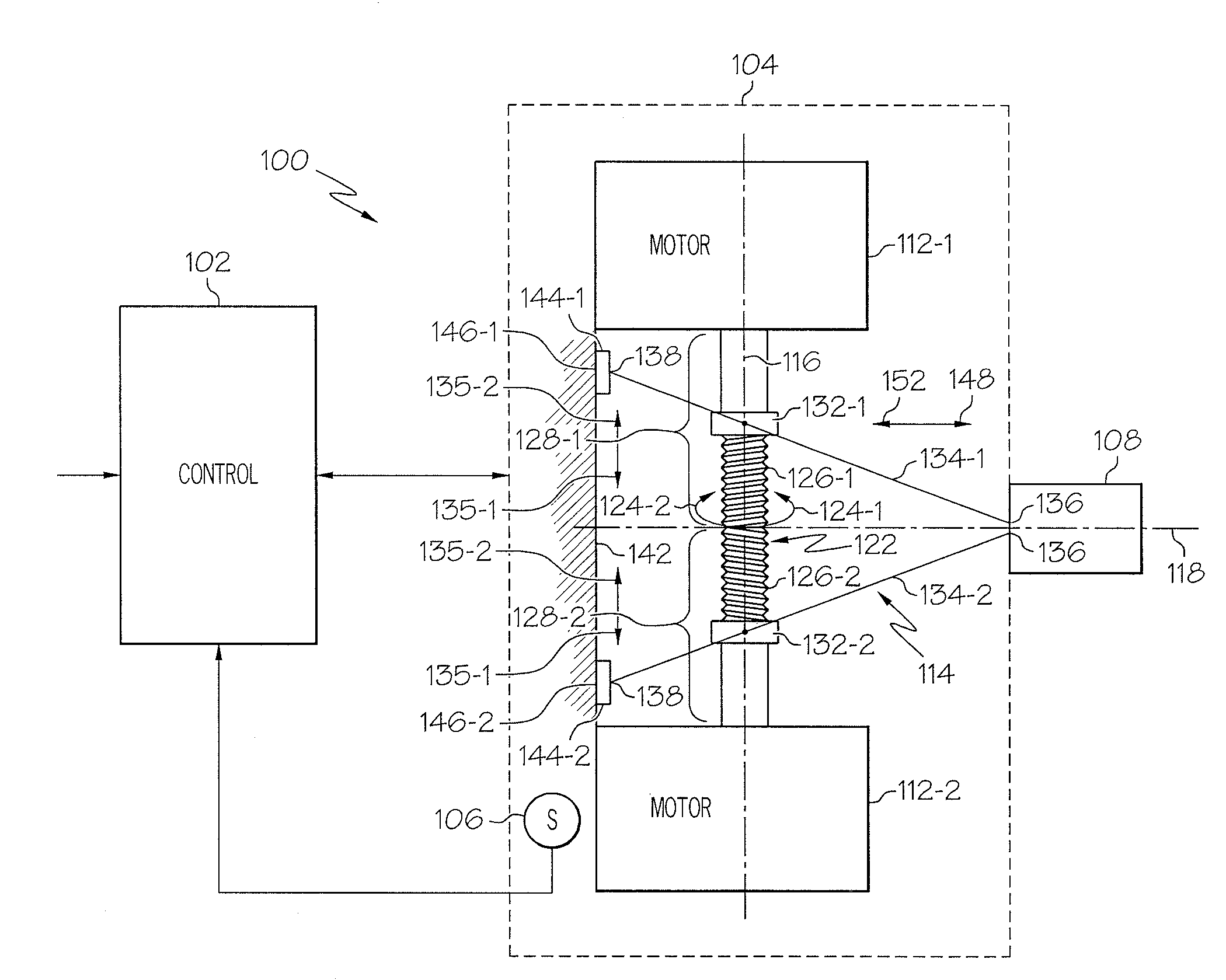
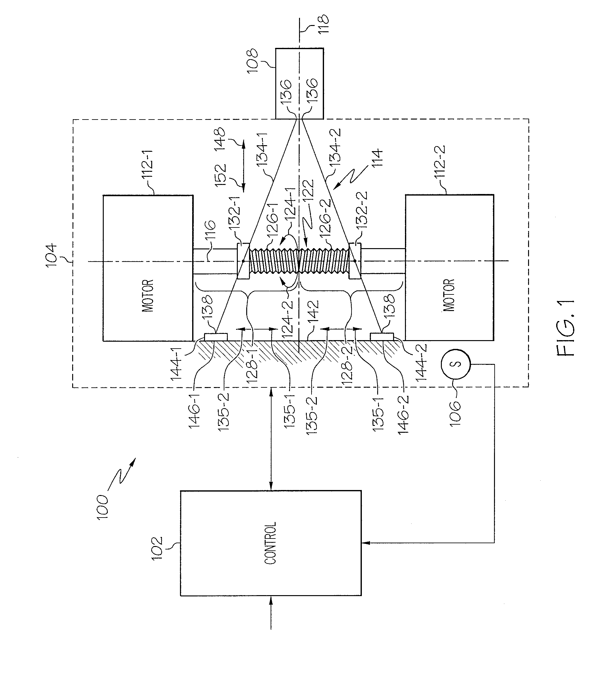
[0017]Referring first to FIG. 1, a functional block diagram of an actuation control system 100 is depicted. The depicted system 100 includes an actuator control 102 and an actuator 104. The actuator control 102 is adapted to receive device position commands from, for example, a non-illustrated external system. In the depicted embodiment, the actuator control 102 also receives feedback signals supplied from one or more sensors 106. In the depicted embodiment only a single sensor 106 is shown since that is all that is needed for control in this embodiment. It will be appreciated, however, that additional sensors 106 may be provided. The actuator control 102, in response to the device position ...


PUM


Abstract

Electromechanical actuators (EMAs) are provided that include an output disposed at a location that is axially central between two EM devices. The EMAs include either one or two motors and an output mechanism. The motors are adapted to be energized and are operable, upon being energized, to either generate torques about a first axis or drive forces along a first axis. The output mechanism is responsive to the torques or forces to translate along a second axis that is perpendicular to the first axis

Description

TECHNICAL FIELD[0001]The present invention generally relates to electromechanical actuators (EMAs) and, more particularly, to an EMA having two motor drives and an output that is centrally disposed between the two motor drives.BACKGROUND[0002]Actuators are used in myriad devices and systems. For example, many vehicles including, for example, aircraft, spacecraft, watercraft, and numerous other terrestrial and non-terrestrial vehicles, include one or more actuators to effect the movement of various control surfaces or components. In many applications such as, for example, aircraft flight surface control systems and missile thrust vector control systems, electromechanical actuators (EMAs) are used. An EMA typically includes an electric motor that, when properly energized, supplies a torque to a suitable actuation device, which in turn positions a control surface or component.[0003]In some applications, there is a need for an EMA having a linear output along an axis that is orthogonal ...

Claims


Application Information

Patent Timeline
IPC IPC(8): H02K7/06F16H25/20
CPCF16H25/20F16H2025/2059H02K7/06H02K16/00Y10T74/1625Y10T74/1633Y10T74/18624Y10T74/18568Y10T74/18608
Inventor JOHNSON, ANDREW T.HANLON, CASEYGECK, KELLAN
Owner HONEYWELL INT INC
Why Eureka
Try Eureka