Electro-mechanical brake system and electro-mechanical brake apparatus used therefor

a technology of electromechanical brakes and brakes, which is applied in the direction of braking systems, automatic initiations, transportation and packaging, etc., can solve the problems of generating danger, revealing safety in the case of parking brakes that are out of order, and not maintaining the stop state of the vehicle, so as to achieve the effect of adding the parking brake function at an affordable pri

Inactive Publication Date: 2007-05-24
HITACHI LTD
View PDF3 Cites 40 Cited by
  • Summary
  • Abstract
  • Description
  • Claims
  • Application Information

AI Technical Summary

Benefits of technology

[0042] In accordance with the structure mentioned above, it is possible to inexpensively add the parking brake function only by installing the single latch mechanism in the electro-mechanical brake a

Problems solved by technology

However, in the structure described in JP-A-2001-206209, there is not disclosed a safety in the case that that the parking brake gets out of order.
However, (1) in the case that a malfunction of the parking brake is identified by outputting a parking brake actuation instruction in a state in which a driver cancels a regular br

Method used


Image

  • Electro-mechanical brake system and electro-mechanical brake apparatus used therefor
  • Electro-mechanical brake system and electro-mechanical brake apparatus used therefor
  • Electro-mechanical brake system and electro-mechanical brake apparatus used therefor

Examples


first embodiment

[0053] A description will be given below of a structure and an operation of an electro-mechanical brake system in accordance with the present invention with reference to FIGS. 1 to 5.

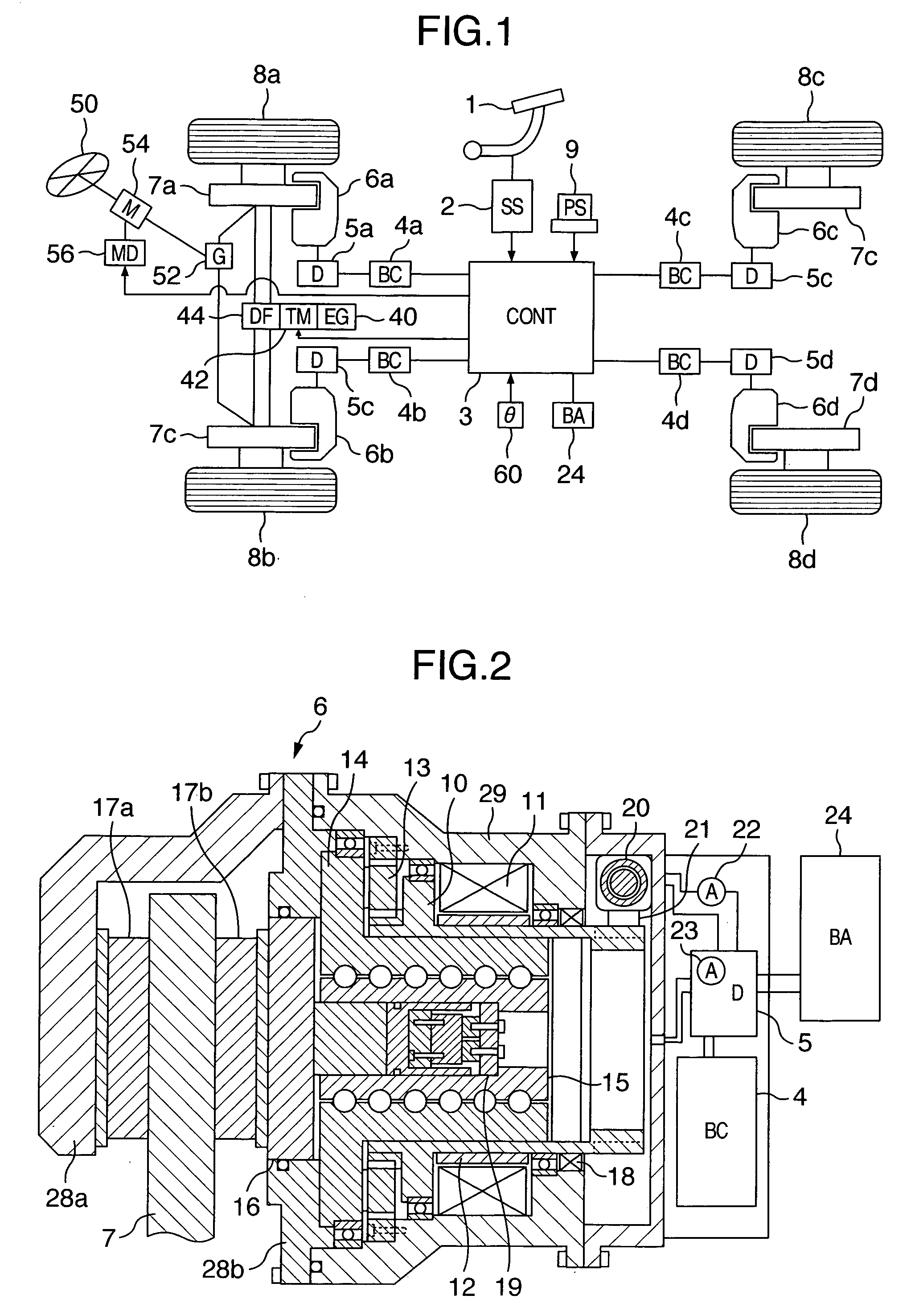
[0054] First, a description will be given of a system structure of the electro-mechanical brake system in accordance with the present embodiment with reference to FIG. 1.

[0055]FIG. 1 is a system block diagram showing the system structure of the electro-mechanical brake system in accordance with the first embodiment of the present invention.

second embodiment

[0056] A driving force of an engine (EG) 40 is shifted by a transmission (TM) 42, is transmitted to each of front wheels 8a and 8b via a differential gear (DF) 44, and rotationally drives the front wheels 8a and 8b. In this case, as a power source, in place of the engine 40, a motor may be employed, or a hybrid system comprising the engine and the motor may be employed. The transmission 42 may be constituted by an automatic transmission or a manual transmission. In this case, at a time of applying a second embodiment mentioned below, it is necessary that the transmission 42 employs an electronically controlled automatic transmission provided with an actuator electronically executing a shift operation, an automatic transmission controlling a change of a shift gear by an actuator, or the like.

[0057] When rotating a steering wheel 50, a rotational driving force is transmitted to the front wheels 8a and 8b via a steering gear 52 so as to steer the front wheels 8a and 8b. As a mechanism ...

third embodiment

[0112] Next, a description will be given of a structure and an operation of an electro-mechanical brake system in accordance with the present invention, with reference to FIGS. 7 and 8. A system structure of the electro-mechanical brake system in accordance with the present embodiment is the same as that shown in FIG. 1. In this case, it is necessary that the road surface slope sensor 60 and the transmission 42 shown in FIG. 1 constitute the electronically controlled automatic transmission provided with the actuator electronically executing the shift operation or the automatic MT controlling the change of the shift gear by the actuator, and the steering wheel 50 is provided so as to control the operating direction of the vehicle body. Further, the structures of the electro-mechanical brake actuators 6a, 6b, 6c and 6d used in the electro-mechanical brake system in accordance with the present embodiment are the same as those shown in FIG. 2. Further, the structure and the operation of...


PUM


Abstract

The invention provides an electro-mechanical brake system which can keep a stop state even if a malfunction is generated in a parking brake, and an electro-mechanical brake apparatus used for the electro-mechanical brake system. An electro-mechanical brake actuator presses a brake pad to a disc rotor so as to independently brake a braking force of each of wheels. A parking brake is constituted by a pawl portion attached to a motor of a motor driving the electro-mechanical actuator and a latch. A main controller detects a failure of the parking brake on the basis of a motor displacement at a time of reducing a motor current, and increases the pressing force in the remaining normal parking brake in the case that the parking brake failure in one wheel or more is detected.

Description

BACKGROUND OF THE INVENTION [0001] (1) Field of the Invention [0002] The present invention relates to an electro-mechanical brake system and an electro-mechanical brake apparatus used for the electro-mechanical brake system, and more particularly to an electro-mechanical brake system preferably employed for a system provided with a parking brake function and an electro-mechanical brake apparatus used for the electro-mechanical brake system. [0003] (2) Description of the Related Art [0004] Conventionally, as a control method of specifying a normal brake line system in the case that a brake line system gets out of order, and carries over a brake control by one brake line system, in an electro-mechanical brake system having two brake line systems, there has been known a method described in patent document 1 (JP-A-2001-206209). In this example, in the case that an ascent of a braking pressure is not detected at a time of a pressure intensifying control in an electronic control brake sys...

Claims


Application Information

Patent Timeline
IPC IPC(8): B60T8/88B60T7/12B60T13/74B60T17/22B62D6/00B62D133/00F16H59/54F16H59/66F16H61/12
CPCB60T7/12B60T13/74F16D65/18F16D2066/003F16D2121/24F16D2125/40F16D2125/50F16D2127/06F16D2129/08
Inventor KAWAHARA, YOSHINARIYOKOYAMA, ATSUSHIKURAGAKI, SATORUOIKAWA, HIROTAKAHIRAKU, KENJI
Owner HITACHI LTD
Why Eureka
Try Eureka