Method of actuating an airplane brake fitted with at least one electromechanical actuator

a technology of electromechanical actuator and airplane brake, which is applied in the direction of automatic braking sequence, braking system, aircraft braking arrangement, etc., can solve the problems of inability to deduce, difficult to measure the force, and much more difficult to implement force servo control

Inactive Publication Date: 2005-05-19
MESSIER BUGATTI INC
View PDF10 Cites 41 Cited by
  • Summary
  • Abstract
  • Description
  • Claims
  • Application Information

AI Technical Summary

Benefits of technology

[0007] An object of the invention is to provide a method of actuating an airplane brake fitted with at least o

Problems solved by technology

In architectures adapted to brakes having electromechanical actuators, each including a pusher which is movable in register with the stack of disks by means of an electric motor for the purpose of exerting a force on the stack of disks in response to a braking reference signal, it is much

Method used


Image

  • Method of actuating an airplane brake fitted with at least one electromechanical actuator
  • Method of actuating an airplane brake fitted with at least one electromechanical actuator

Examples


Embodiment Construction

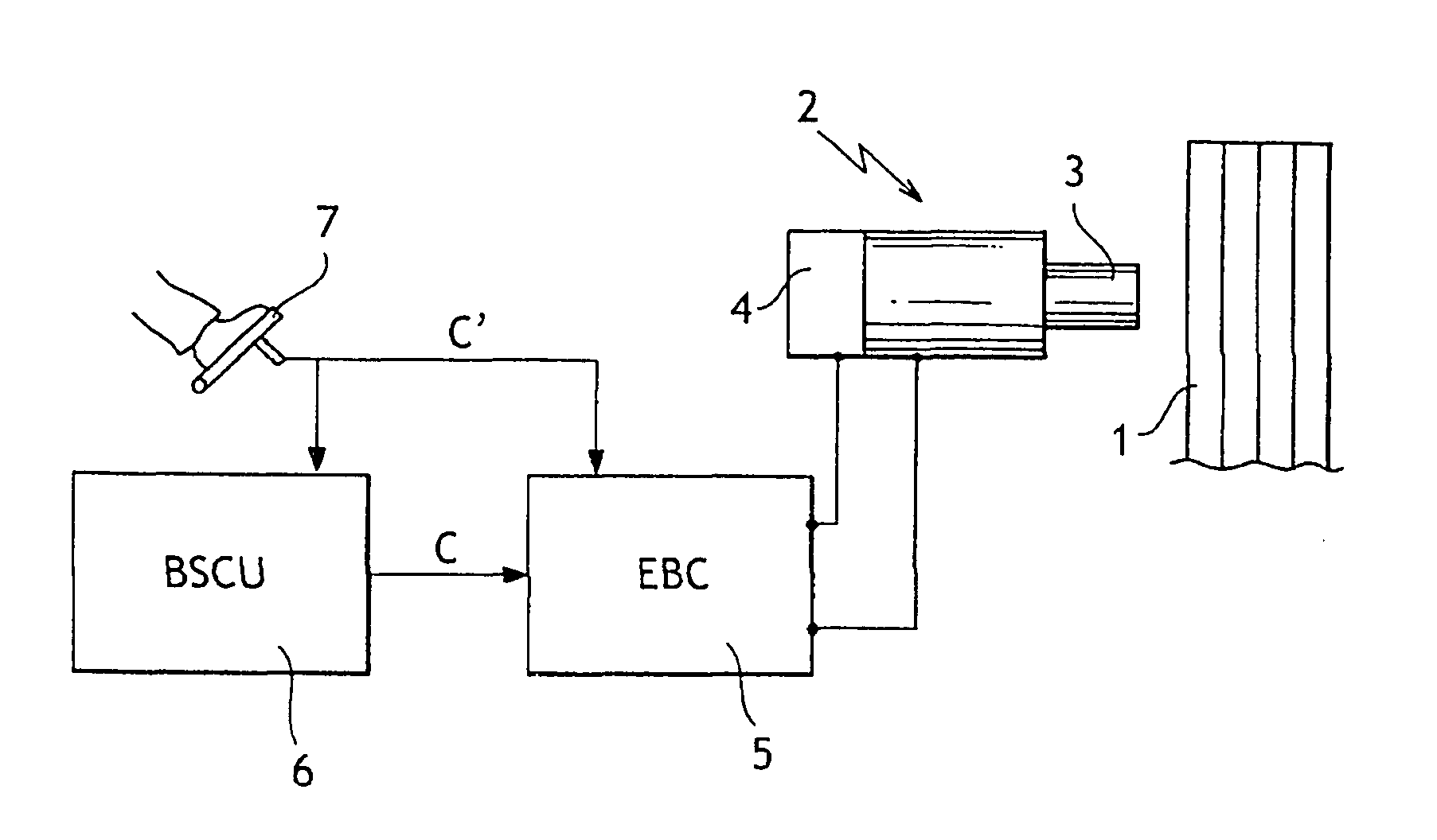
[0028] With reference to FIG. 1, electromechanical brakes for an airplane comprise a stack of disks 1 having at least one electromechanical actuator 2 facing the stack. The actuator 2 comprised an electric motor (not shown) which actuates a pusher 3 that is movable in register with the stack of disks 1 in order to apply a braking force thereto.

[0029] In this case, the actuator 2 includes a locking member 4 for locking the pusher 3.

[0030] The actuator 2 is associated with a control unit 5 (referenced EBC in the figure) which is adapted to control the locking member 4 and to power the electric motor of the actuator 2 as a function of a braking reference signal C generated by a braking calculator 6 (referenced BSCU in the figure).

[0031] The braking reference signal C is generated by the braking calculator 6 as a function of signals coming from brake pedals 7 actuated by the pilot of the airplane. In an emergency mode of operation when the braking calculator BSCU 6 has failed, the pe...


PUM


Abstract

The invention provides a method of actuating an airplane brake fitted with at least one electromechanical actuator including a pusher that can be displaced in controlled manner in register with a stack of disks to apply a force on the stack of disks in response to a braking reference signal, the method comprising the steps of: when the braking reference signal crosses a contact threshold, controlling the actuator so that the pusher approaches the stack of disks, until the pusher reaches a contact position with the stack of disks; storing said contact position; and then immediately afterwards, controlling the actuator so that the pusher applies a force on the stack of disks in response to the braking reference signal.

Description

[0001] The invention relates to a method of actuating an airplane brake fitted with at least one electromechanical actuator. BACKGROUND OF THE INVENTION [0002] In braking architectures for airplanes fitted with hydraulic brakes, it is known to control the pistons under force servo-control. To implement such servo-control, the force exerted by the pistons is derived very simply from a measurement of the pressure applied by the airplane hydraulic circuit to the pistons. [0003] In architectures adapted to brakes having electromechanical actuators, each including a pusher which is movable in register with the stack of disks by means of an electric motor for the purpose of exerting a force on the stack of disks in response to a braking reference signal, it is much more difficult to implement force servo-control. [0004] Measuring the force is difficult because it is no longer possible to deduce the force from a measurement of the pressure of a fluid. That makes it necessary to implement s...

Claims


Application Information

Patent Timeline
IPC IPC(8): B60T7/04B60T8/17B60T13/74B64C25/42
CPCB60T7/042B64C25/426B60T13/74B60T8/1703
Inventor CHICO, PHILIPPEGIROD, PIERRE
Owner MESSIER BUGATTI INC
Why Eureka
Try Eureka