
Miniature pressure transducer

a technology of pressure transducers and miniature bodies, applied in the direction of fluid pressure measurement, fluid pressure measurement by electric/magnetic elements, instruments, etc., can solve the problems of significant leakage current, limited arrangement, and limited pressure sensors etched onto silicon wafers

Inactive Publication Date: 2010-03-25
AMPHENOL THERMOMETRICS
View PDF9 Cites 9 Cited by
  • Summary
  • Abstract
  • Description
  • Claims
  • Application Information

AI Technical Summary

Benefits of technology

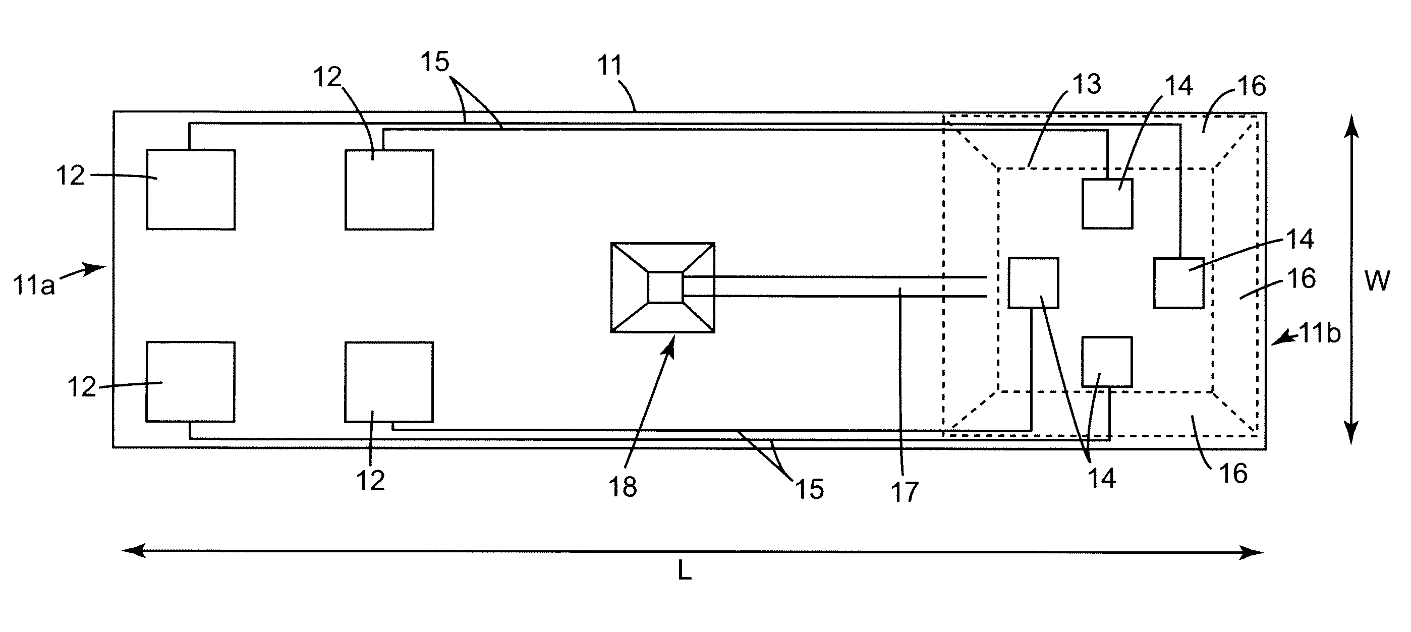
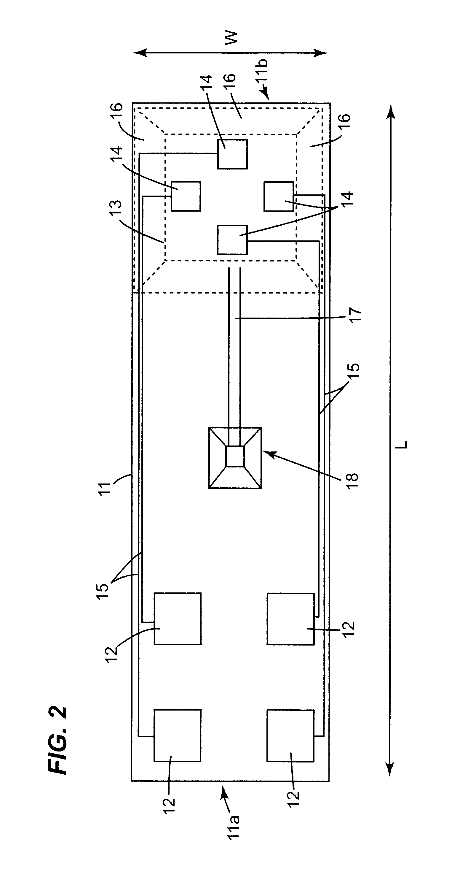
[0011]As the base portion is elongate and the diaphragm extends across substantially the entire effective width of the base portion at the distal end, with the contact areas formed at the opposite end of the base portion, the diaphragm is as large and thus as sensitive as it can be for that width of base portion. Consequently, a pressure sensor using this base portion will have a compact width without loss of pressure sensing capability. This is in contrast to conventional sensor substrates in which the diaphragm does not extend across substantially the entire effective width of the base portion, often due to the positioning of contact areas around the diaphragm.
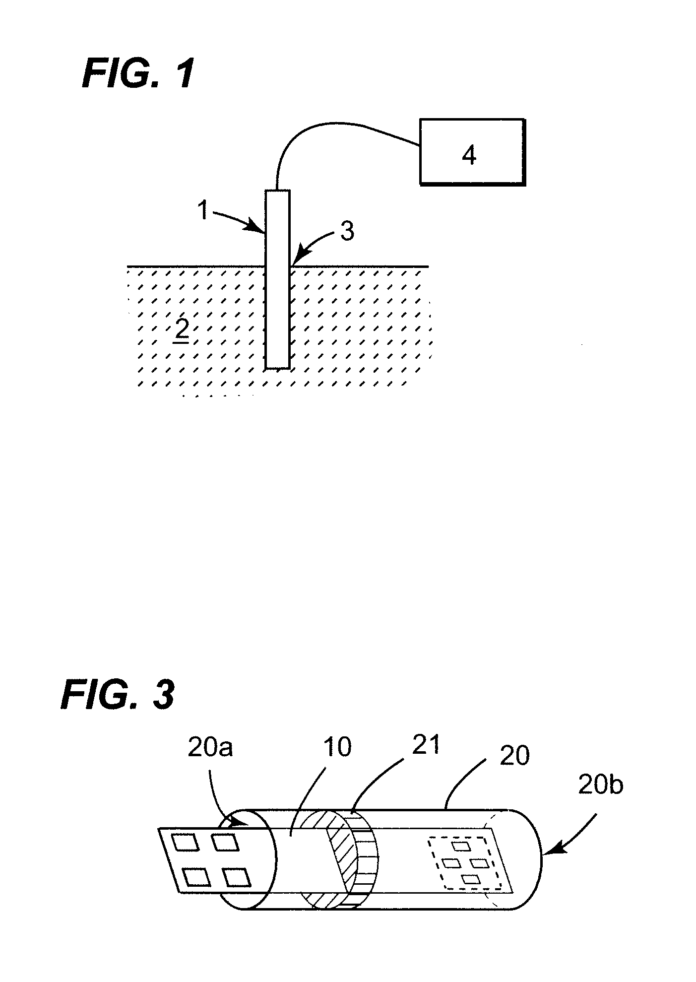
[0015]In order to prevent fluid to be measured from coming into contact with the contact areas, wire bonds and cables, the substrate may be provided in a protective cover, such as a tube, with a seal provided between the substrate and the protective cover at a point along the elongate length of the base portion between the diaphragm and the contact areas. The protective cover and seal preferably have similar or substantially matched thermal expansion properties to the base portion comprising silicon, so that they may be used over a large range of temperatures without compromising the seal or causing excessive stress to the substrate. The protective cover, may for example, comprise titanium or Kovar and the seal may comprise a glass frit. Even if there is some stress produced in the base portion due to thermal mismatch during use, as the base portion is elongate with the diaphragm formed at the distal end, any stress in the area of the seal should not affect measurements at the diaphragm.

Problems solved by technology

Furthermore, pressure sensors etched onto silicon wafers are generally limited by the temperature range at which they can operate.
One reason for this is that semiconductor junctions of tracks and piezoresistors doped into the silicon produce significant leakage currents at increasing temperatures degrading the signals received from the piezoresistors.
However, such an arrangement is also limited by the temperature at which it can operate because at increasing temperatures the oil expands interfering with flexing of the diaphragm and reducing the precision of measurements produced.
Furthermore, the silicon sensor is generally attached using an adhesive which cannot withstand the high temperatures, either failing in strength or outgassing reducing the precision in the oil filled package.

Method used


Image

  • Miniature pressure transducer
  • Miniature pressure transducer
  • Miniature pressure transducer

Examples


Embodiment Construction

[0024]As can be seen in FIG. 1, a pressure transducer 1 including a substrate according to an embodiment of the present invention may be inserted into a fluid 2 so that the pressure of the fluid may be measured. The elongate base portion of the substrate enables elongate pressure transducers 1 to be produced which may be easily and conveniently inserted through access holes 3 into fluid. For example, a pressure transducer may be conveniently inserted through the wing of an aircraft to be brought into contact with fluid within the wing. The pressure transducer 1 may be used in many other situations such as to sense the pressure of fluids flowing through conduits or in reservoirs used in the automotive industry and many applications in the medical industry. The transducer 1 of FIG. 1 is connected to a suitable control device 4 such as a microprocessor to determine the pressure of the fluid 2 to which it is exposed.

[0025]FIG. 2 schematically shows a top view of a substrate 10 which may...


PUM


Abstract

A miniature pressure transducer is disclosed which is able to operate at high temperatures. The pressure transducer is provided on a substrate comprising an elongate silicon base portion with one or more contact areas formed at one end and a diaphragm formed at the opposite distal end. A plurality of piezoresistive elements are provided on the diaphragm, preferably in a Wheatstone Bridge arrangement, and connected to the contact areas using interconnects. The diaphragm extends across substantially the entire effective width of the elongate base portion providing a compact width whilst still maintaining a sensitive pressure sensing capability.

Description

FIELD AND BACKGROUND OF THE INVENTION[0001]This invention relates to pressure transducers, in particular to miniature pressure transducers provided on a silicon wafer able to operate at high temperatures.[0002]Pressure transducers etched or “micromachined” onto a silicon wafer are significantly smaller than conventional pressure transducers. Because of their small size, such micromachined pressure transducers are able to be used in situations that would be impractical for a conventional sensor such as, for example, in particular applications in the aereospace, medical or automotive industries.[0003]U.S. Pat. No. 6,629,465 discloses the preparation of pressure transducers from a silicon wafer. Such sensors involve etching a cavity into a silicon wafer to expose a thin silicon diaphragm supported over a silicon frame. The silicon diaphragm may be exposed to a pressure to be measured and will flex in a predetermined manner depending upon the pressure to which it is exposed. The flexing...

Claims


Application Information

Patent Timeline
IPC IPC(8): H01C10/10
CPCG01L19/0069G01L9/0054
Inventor CRADDOCK, RUSSELLKING, JAMES ANTHONY
Owner AMPHENOL THERMOMETRICS
Learn More