
Controlling data access to and from an RFID device

a technology of radio frequency identification and data access, applied in the direction of program control, testing/monitoring control system, instruments, etc., can solve the problem of only being able to communicate with the rfid device, and achieve the effect of effective and reliable password security and password management system, effective prevention, and easy inspection of product integrity

Active Publication Date: 2010-03-25
BEIJING XIAOMI MOBILE SOFTWARE CO LTD
View PDF19 Cites 60 Cited by
  • Summary
  • Abstract
  • Description
  • Claims
  • Application Information

AI Technical Summary

Benefits of technology

The present invention provides a method for controlling data access to an RFID device with a data memory and a physical uncloneable function (PUF). The method involves sending a first challenging signal to the RFID device, producing a first response signal based on the first challenging signal, storing the first response signal in the data memory of the RFID device, sending a second challenging signal, and producing a second response signal. The first and second response signals are compared to verify if they are identical. The method allows for effective restriction of data communication with the RFID device and prevents or minimizes copying and counterfeiting of the RFID device and products in the supply chain. The PUF can be a silicon PUF or a coating PUF, and the challenge for the PUF can be a digital input signal. The technical effect of the invention is to provide a secure and effective method for controlling data access to RFID devices.

Problems solved by technology

As a consequence, the communication with the RFID device is only possible if the first and the second response signals are identical, because due to the above-described characteristic of the physical uncloneable function an unpredictable but unique response signal is generated for each challenging signal.

Method used


Image

  • Controlling data access to and from an RFID device
  • Controlling data access to and from an RFID device
  • Controlling data access to and from an RFID device

Examples


Embodiment Construction

[0068]The illustration in the drawing is schematically. It is noted that in different figures, similar or identical elements are provided with the same reference signs or with reference signs, which are different from the corresponding reference signs only within the first digit.

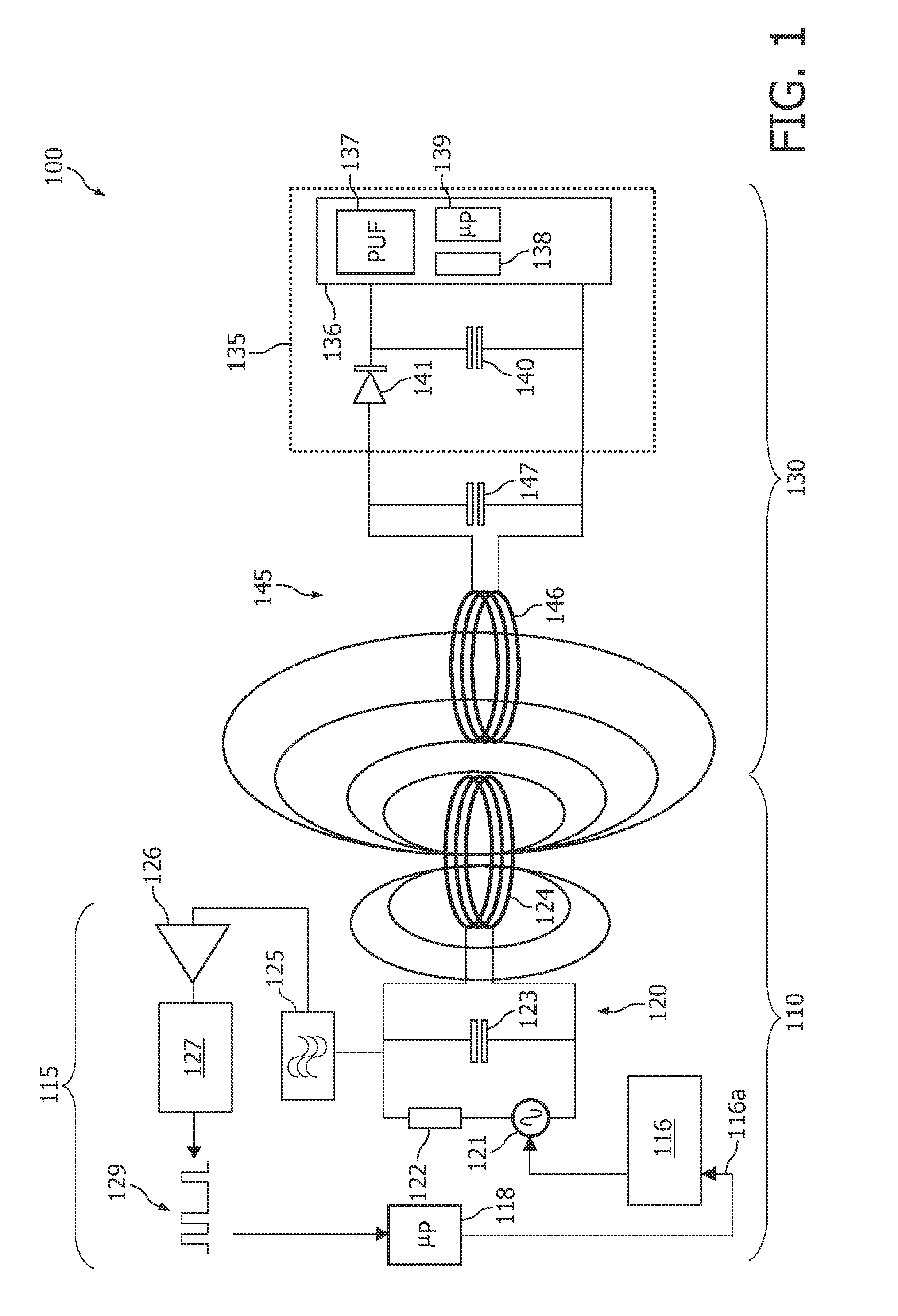
[0069]FIG. 1 shows an RFID system 100 comprising an RFID reading device 110 and an RFID device 130 according to an embodiment of the invention. The RFID device might also be denoted an RFID tag 130.

[0070]The RFID reading device 110 comprises an electronic circuit 115 and an antenna 124. The antenna 124 is used both for transmitting RF radiation signals to the RFID device 130 and for receiving RF radiation signals backscattered from the RFID device 130.

[0071]The electronic circuit 115 comprises a so-called Amplitude Shift Keying (ASK) modulator 116. The operation of the ASK modulator 116 can be triggered by a drive signal 116a. The drive signal 116a is directly or indirectly generated by a data processor 118 ...


PUM


Abstract

It is described a method for controlling data access to and from an RFID device (230). Thereby, an RFID reading device (210b) authenticates himself to the RFID device (230) before the RFID device (230) communicates with the RFID reading device (210b). The RFID device (230) is equipped with a physically uncloneable function (237), which is adapted to produce a unique but unpredictable response signal (R1, R2) upon receiving a predefined challenging signal (C1, C2). During an enrolment of the RFID device a first response signal (R1) being uniquely associated with a first challenging signal (C1) is stored in a memory (238) of the RFID device (230). The first challenging signal (C1) represents a password for opening further data communication with the RFID device (230). When a RFID reading device queries the RFID device (230) with a second challenging signal (C2), the RFID device (230) compares the corresponding response signal (R2) with the response (R1) being stored during enrollment and only if there is a match, responds with its identifier (ID).

Description

FIELD OF INVENTION[0001]The present invention relates to the field of Radio Frequency Identification (RFID) devices. Specifically the present invention relates to a method for controlling the data access to and from an RFID device in particular in order to check the integrity of the RFID device and / or to check the integrity of a product being equipped with the RFID device.[0002]Further, the present invention relates to an RFID device comprising a physical uncloneable function, which RFID device is adapted to be used for carrying out the above-described method for controlling the data access to and from an RFID device.[0003]Furthermore, the present invention relates to an RFID reading device and an RFID system both being adapted to be used for carrying out the above-described method for controlling the data access to and from an RFID device.ART BACKGROUND[0004]Radio Frequency Identification (RFID) is an emerging technology with numerous applications, e.g. as smart labels or tags. RFI...

Claims


Application Information

Patent Timeline
Patent Type & Authority Applications(United States)
IPC IPC(8): H04Q5/22
CPCG06K19/07309H04L2209/805H04L9/3278
Inventor GUAJARDO MERCHAN, JORGECONRADO, CLAUDINE VIEGAS
Owner BEIJING XIAOMI MOBILE SOFTWARE CO LTD
Learn More