In-station control system and method

a control system and in-station technology, applied in the field of in-station control techniques, can solve the problems of difficult to map a large amount of control signal, difficult to install more terminal interfaces, complex installation of dedicated-line cables for control data, etc., and achieve the effect of avoiding the interruption of control data communication

Inactive Publication Date: 2002-01-29
FUJITSU LTD
View PDF5 Cites 1 Cited by
  • Summary
  • Abstract
  • Description
  • Claims
  • Application Information

AI Technical Summary

Benefits of technology

is to provide a control data communications system which permits communications cables to be installed readily even if the configuration of an exchange system becomes large, avoids the interruption of control data communications even when a fault occurs in a highway for transmitting subscriber cells, and permits a large number of control signals which may occur irregularly to be transmitted over a dedicated line in an efficient manner.
Furthermore, since the control data is transferred over the control link synchronously with the highway clock on the subscriber link, there is no need of providing anew a special control line and a clock controller for synchronizing the control link, permitting the system hardware scale to be reduced. In general, in an ATM exchange system and the like the frequency of the highway clock is very high, which permits high-speed control data communications with no need for an additional clock controller for the control link.
According to the second mode of the invention, the use of the second data transfer time interval allocated to the signal line permits a small number of specific control signals having real-time requirements for device resetting, fault notification, and the like to be communicated efficiently between the two devices as in the prior art techniques and moreover the use of the first data transfer time interval allocated to the signal line permits a large number of control signals which may occur irregularly, such as subscriber traffic information, to be transferred.

Problems solved by technology

However, the first prior art technique has a problem that the installation of dedicated-line cables for control data becomes more complex as the configuration of an exchange system grows larger and hence it is not so easy to install more terminal interfaces 105.
However, when the above-described conventional technique is applied to transmission of such control signal, a problem arises in that it is difficult to map a large amount of control signal that may occur irregularly on the data time intervals on the dedicated lines.
In the second prior art technique, however, not only subscriber cell communications but also control cell communications will be stopped in the event that the highway 206 that transmits subscriber cells develops a fault.
In the event of such a highway fault, it becomes impossible to acquire fault information, which makes it difficult to pinpoint a faulty component and retards recovery from the fault.

Method used


Image

  • In-station control system and method
  • In-station control system and method
  • In-station control system and method

Examples


first embodiment

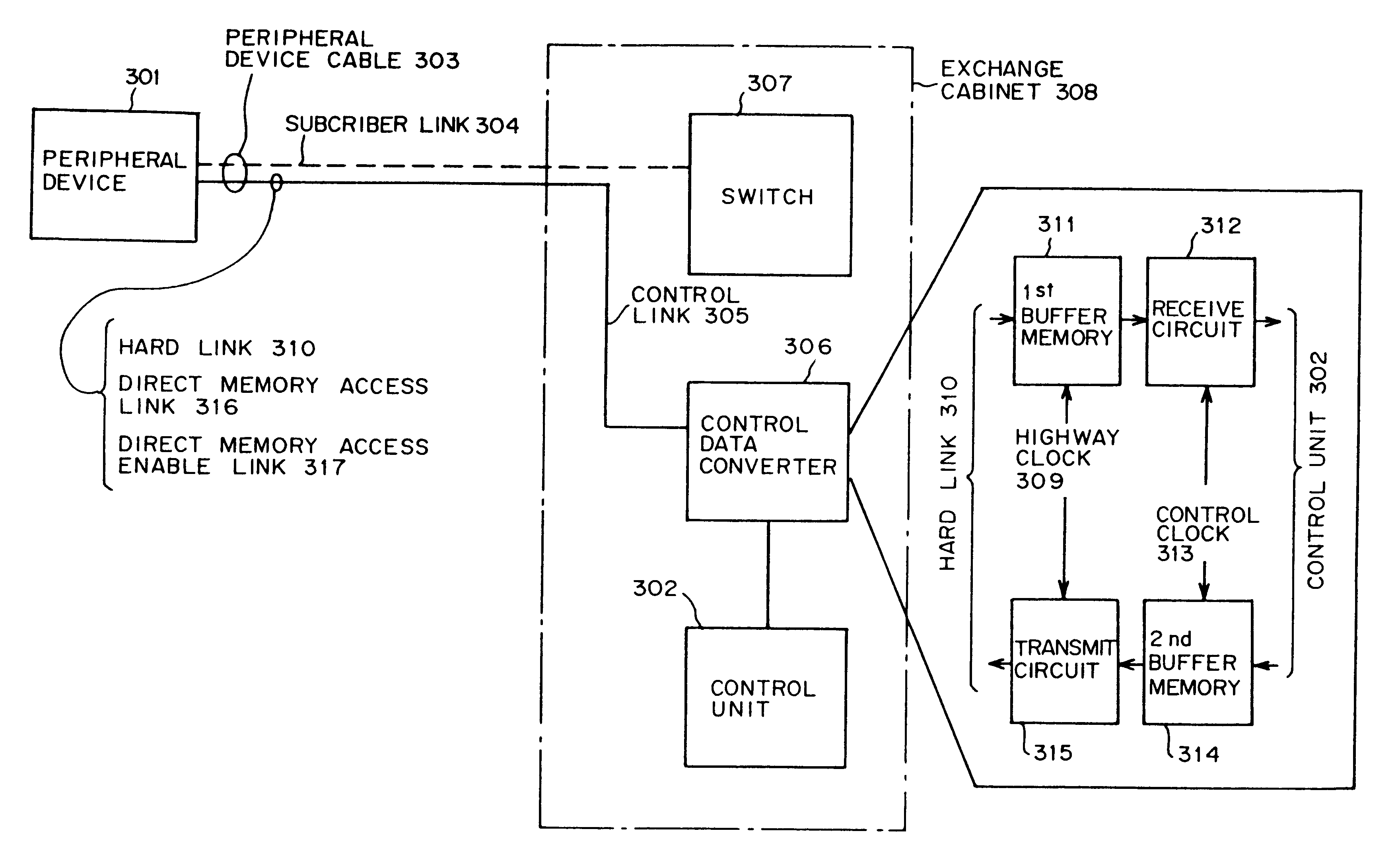
Here, a second feature of the present invention is that the control link 504 is composed of a hard link, a DMA link, and a DMA enable link. Although, in the invention, each of these links comprises a physical line for one bit, the hard link and the DMA link each may comprise a plurality of physical lines for multiple bits. The hard link is a link used to transfer control data by means of so-called refreshing. The refreshing is a method to transfer the states of specific types of control data at regular intervals. In contrast, the DMA link is a link for transferring control data by the DMA transfer method. The DMA enable link is a link for controlling the transfer of the DMA link. Such a characteristic configuration permits information that has a high level of redundancy but requires a high level of stability and information that needs broadcasting to be transferred over the hard link and a large amount of control data, such as traffic information, to be transferred over the DMA link...

second preferred embodiment

Next, a description will be given of a second preferred embodiment of the present invention that is related with the second mode of the present invention shown in FIG. 4.

FIG. 15 is a block diagram of the second preferred embodiment of the present invention. The second preferred embodiment is an application of the second mode of the invention to control signal communications between #0- and #1-system subscriber interface common sections 201 and a subscriber interface individual section 202, which are internal duplex devices within an ATM exchange.

The second preferred embodiment of the invention shown in FIG. 15 differs from the first preferred embodiment of the invention shown in FIG. 5 in that a subscriber control highway in FIG. 15 that corresponds to a control link 504 of FIG. 5 consisting of two physical lines- a hard link and a DMA link-consists of a single physical line.

In FIG. 15, each of the #0- and #1-system subscriber interface common sections 201 accommodates a plurality o...

second embodiment

In the second embodiment, the present invention is applied to control signal communications between the #0- and #1-system subscriber interface common sections 201 and the subscriber interface individual section 202, which are internal duplex devices of an ATM exchange. This is not restrictive. Of course, it is also possible to apply the present invention to control signal communications between subscriber interface common sections in an ATM exchange and a central control unit.

In this case, as with the first preferred embodiment, it is also possible to connect a subscriber interface common section and an ATM switch by a terminal interface cable which integrally incorporates a main signal (subscriber cell) transmission line ad a control signal transmission line.

Furthermore, the present invention need not be applied only to an ATM exchange but can be applied to control signal communications between internal devices in various systems.


PUM


Abstract

A peripheral device cable, connected to a peripheral device, integrally incorporates a subscriber link that is a physical line for transmitting subscriber information in synchronization with a highway clock and a control link that is a physical line for transmitting control data in synchronization with the highway clock. A control data converter controls interfacing between the control data transferred over the control link synchronously with the highway clock and control data that a control unit transmits / receives asynchronously with the highway clock. The subscriber link is connected to a switch.

Description

1. Field of the InventionThe invention relates to in-device control techniques including an in-station control technique used in an exchange station, such as an ATM exchange, that controls communications of control data between a peripheral device, such as a terminal interface, that accommodates a subscriber line and a control unit that controls the entire exchange station.2. Description of the Related ArtIn an exchange, in order to control peripheral devices, such as terminal interfaces, that are attached to a channel switch and accommodate subscriber lines, it is required to communicate control data between a control unit, such as a processor, that controls the entire exchange and the terminal interfaces.FIG. 1 is a block diagram showing a first prior art technique for such control data communications. In this prior art technique, in addition to a highway 106 that is connected between a channel switch (SW) 101 and each terminal interface (TERM) 105 and transmits subscriber data, a...

Claims


Application Information

Patent Timeline
Patent Type & Authority Patents(United States)
IPC IPC(8): H04L12/56
CPCH04L12/56
Inventor KIRA, MASAKISAMEJIMA, NORIKOMORITA, YOSHIOURIU, SHIRO
Owner FUJITSU LTD
Why Eureka
Try Eureka