Antenna arrangement

a technology for antennas and earthing switches, applied in the direction of antenna earthing switches, antenna supports/mountings, antenna earthing switches, etc., can solve the problem of difficult to obtain a low-volume antenna arrangemen

Active Publication Date: 2010-03-25
RPX CORP
View PDF5 Cites 22 Cited by
  • Summary
  • Abstract
  • Description
  • Claims
  • Application Information

AI Technical Summary

Benefits of technology

[0006]The interconnection of the first part of the ground plane with the second part of the ground plane using a component controls the electrical length of the ground plane and its resonant frequencies. Electric currents flowing within the ground plane between the first part and the second part are channelled through the component. The use of an inductive coupling element adjacent this ‘channel’ enables strong inductive coupling between the ground plane and the coupling element.

Problems solved by technology

It is therefore difficult to obtain a low volume antenna arrangement that has satisfactory performance.

Method used


Image

  • Antenna arrangement
  • Antenna arrangement
  • Antenna arrangement

Examples


Embodiment Construction

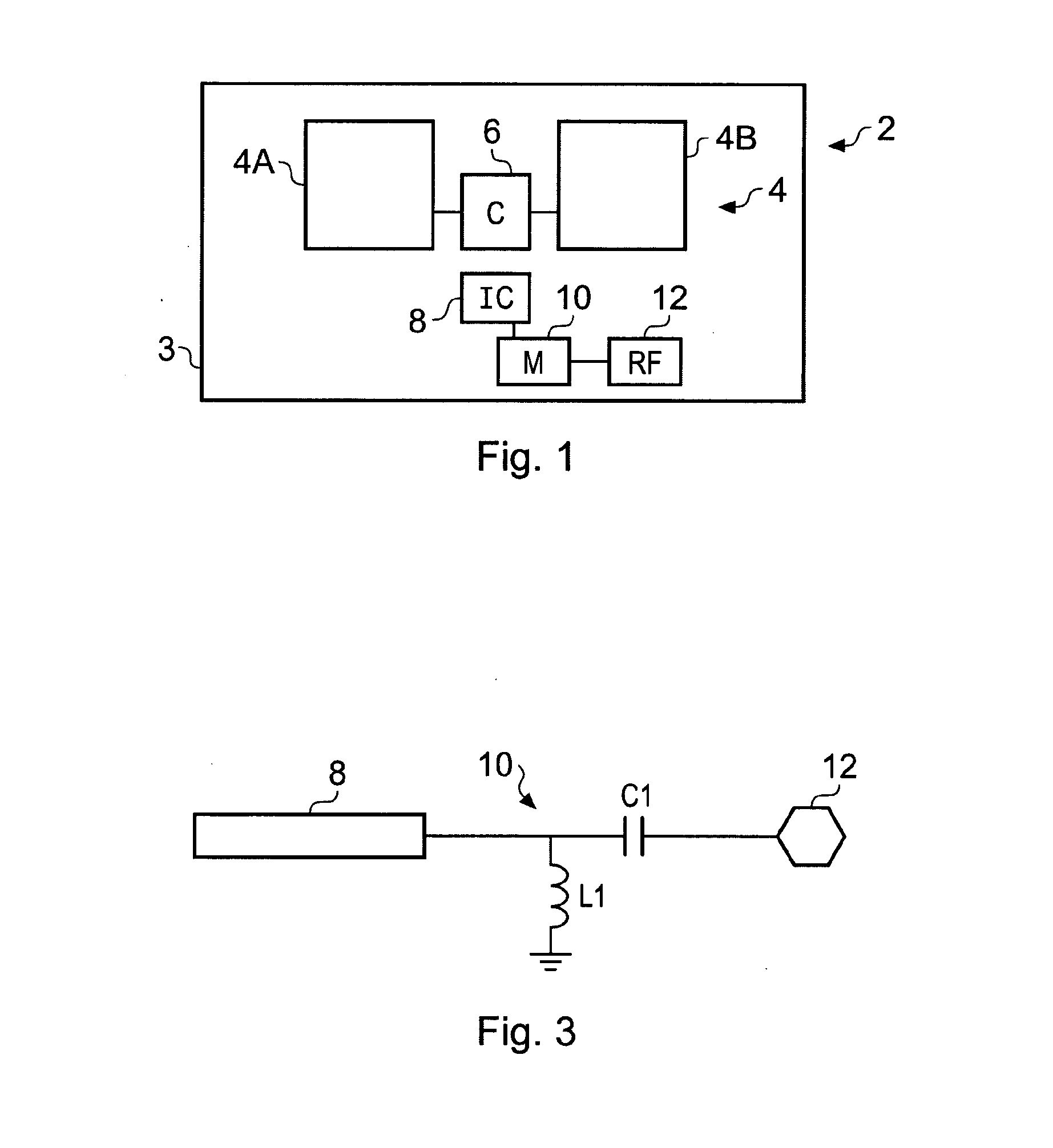
[0021]FIG. 1 schematically illustrates an electronic device 3 such as a portable electronic device or wireless communication device or a module for such an electronic device.

[0022]The device (or module) 3 comprises an antenna arrangement 2 for transmitting and / or receiving radio frequency (RF) communication signals.

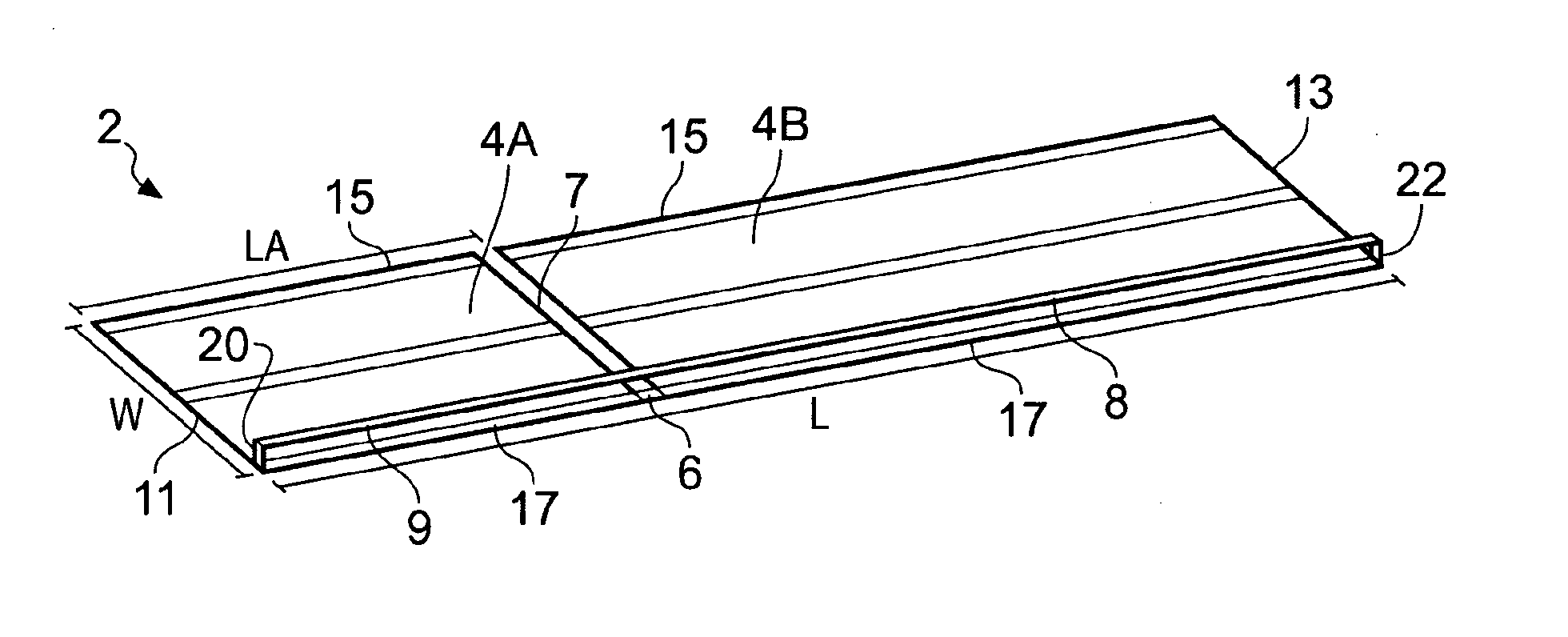
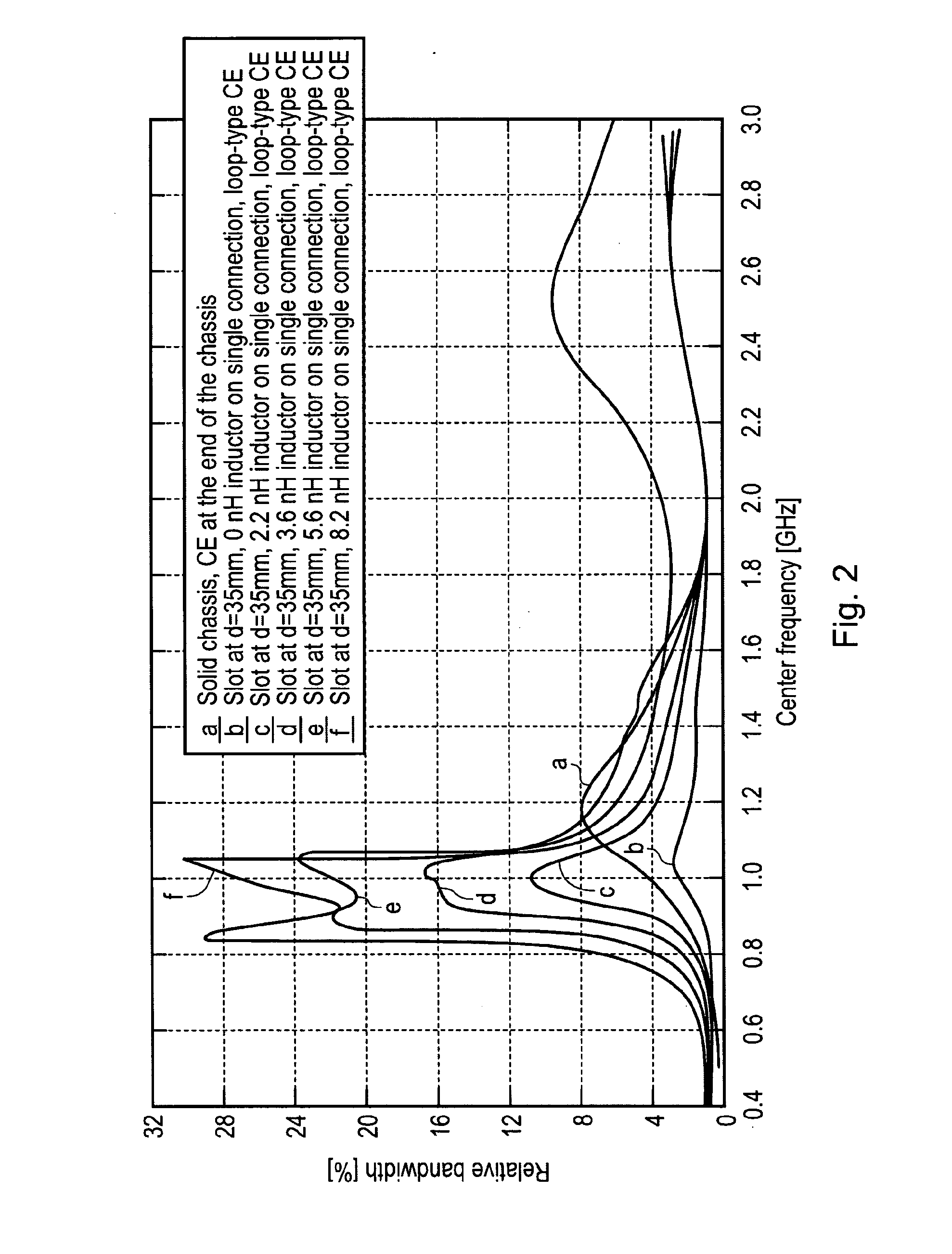
[0023]The illustrated antenna arrangement 2 is a low-volume, low-profile antenna arrangement that has a wide operational bandwidth at a resonant frequency. This may enable use of the antenna arrangement 2 for communication in one or more communication bands that lie within that bandwidth.

[0024]Examples of suitable communication bands include: AM radio (0.535-1.705 MHz); FM radio (76-108 MHz); Bluetooth (2400-2483.5 MHz); WLAN (2400-2483.5 MHz); HLAN (5150-5850 MHz); GPS (1570.42-1580.42 MHz); US-GSM 850 (824-894 MHz); EGSM 900 (880-960 MHz); EU-WCDMA 900 (880-960 MHz); PCN / DCS 1800 (1710-1880 MHz); US-WCDMA 1900 (1850-1990 MHz); WCDMA 2100 (Tx: 1920-1980 MHz Rx: 2110-2180...


PUM


Abstract

An antenna arrangement including a partitioned ground plane including at least a first part and a second part that are interconnected by a component having a predetermined impedance; and an inductive coupling element positioned adjacent the component.

Description

FIELD OF THE INVENTION[0001]Embodiments of the present invention relate to an antenna arrangement and / or a method. In particular, they relate to a low-volume, wideband antenna arrangement.BACKGROUND TO THE INVENTION[0002]It is generally desirable to create antenna arrangements that occupy low volumes so that they can be easily integrated within electronic devices or modules for electronic devices.[0003]As the volume of an antenna arrangement decreases the bandwidth of the antenna arrangement at its lower resonant frequency can decrease.[0004]It is therefore difficult to obtain a low volume antenna arrangement that has satisfactory performance.BRIEF DESCRIPTION OF THE INVENTION[0005]According to some embodiments of the invention there is provided an antenna arrangement comprising: a partitioned ground plane comprising at least a first part and a second part that are interconnected by a component having a predetermined impedance; and an inductive coupling element positioned adjacent t...

Claims


Application Information

Patent Timeline
Patent Type & Authority Applications(United States)
IPC IPC(8): H01Q1/50
CPCH01Q1/48H01Q1/243
Inventor OLLIKAINEN, JANIVILLANEN, JUHAHOLOPAINEN, JARI PETTERIICHELN, CLEMENSVAINIKAINEN, PERTTI
Owner RPX CORP
Why Eureka
Try Eureka