
Systems and Methods for Detecting Unsafe Thermal Conditions in Wiring Devices

Inactive Publication Date: 2010-03-25
ENERGY SAFE TECH
View PDF28 Cites 26 Cited by
  • Summary
  • Abstract
  • Description
  • Claims
  • Application Information

AI Technical Summary

Benefits of technology

[0012]Implementation of the invention provides improved detection of series fault conditions, and provides improved response possibilities upon detection of such conditions. Some implementations of the invention utilize electronic temperature sensors such as solid-state sensors and temperature sensors integrated into an integrated circuit. In some implementations, the electronic temperature sensors are connected to a printed circuit board (PCB) that is connected to supply wire connectors, and in other implementations they are directly connected to supply wire connectors. In some implementations, differential temperature sensing, as an alternative to or in addition to direct temperature sensing, is provided.
[0013]The electronic temperature sensors can be quite small, and can therefore be located more closely to or directly on the supply wire connectors, which improves the rapidity with which localized heating can be detected. As the electronic sensors can be connected to PCBs and to other circuits, functionalities can be implemented using the PCBs and / or other circuits that cannot be provided with simple switching-type thermal sensors. Non-limiting examples of such additional functionality include integrated ground-fault detection, integrated safety features such as open-circuit, short-circuit, and ground fault detection, and integrated notification of detected fault conditions.
[0014]Electronic sensors in accordance with implementations of the present invention are capable of detecting overheating conditions at temperatures below those detected by current bimetallic temperature sensors, thereby improving the safety of electrical wiring devices and fixtures. Additionally, using electronic sensors, the threshold temperature for response can be selected or controlled to be at a variety of temperatures, including temperatures lower than those available with current bimetallic switching sensors. Detecting heating events and disconnecting power at lower temperatures improves safety. Implementations of the invention may be incorporated into any type of wired electrical device, electrical fixture, or wiring device.

Problems solved by technology

Many building fires occur because of unsafe heating associated with power outlets, light switches or other fixture.
For example, loose connections cause points of excessive heating under normal use.
If not detected, this localized heating leads to fires by igniting wire insulation, fixture materials, framing, or other nearby flammable objects.
The fires caused by the excessive localized heating result in property loss, injury and even death.
The excessive heating happens for one of several different reasons that include: an installer who neglects to tighten or fully tighten screws on the supply wires, regular use that loosens supply wire connections, supply wire connection materials that become oxidized, an unqualified installer who connects supply wires improperly, components involved in making or breaking an electrical connection wearing with use, localized arcing associated with making or breaking an electrical connection causes oxidation of the involved components, and / or poor construction of the involved components.
Any of these conditions / causes leads to unexpected electrical resistance at the connection point, and electrical current flowing through the higher-than-expected electrical resistance causes the overheating and fires described above.
In some instances, abnormally-high electrical resistance may develop over time, leading to overheating.
The left-most screw of the illustrated plug receptacle was not tightened sufficiently and overheated, melting the insulation on the supply wire.
Furthermore, the screw oxidized, increasing the excessive heating and leading to melted plastic and a destructive fire.
When the electrical current is interrupted, the power delivered to the high-resistance connection stops, along with the heating generated by the power lost at the connection.
Such devices have proved difficult to implement.
While most plastic household wiring insulation and outlet housings do not melt until temperatures reach or exceed approximately 300 degrees Fahrenheit, operation approaching 200 degrees Fahrenheit has a high probability of causing distortion of the materials.
Because of the bulk of typical bimetallic switches, it is difficult to locate such switches close to the locations of potential heating, and thus such bimetallic switches fail to adequately protect against over-heating even when they have a lower temperature threshold for switching.
Such attempts lead to higher manufacturing costs and also fail to address the fact that the 200-degree threshold of the bimetallic thermal switching, while preventive of fires, fails to prevent material distortion with its attendant risks and difficulties.
Current circuit breakers and fuses are unable to detect points of excessive heating, because they measure electric current rather than temperature.
AFCI devices do not provide protection against series faults that lead to glowing connections (overheating) and subsequent fires.

Method used


Image

  • Systems and Methods for Detecting Unsafe Thermal Conditions in Wiring Devices
  • Systems and Methods for Detecting Unsafe Thermal Conditions in Wiring Devices
  • Systems and Methods for Detecting Unsafe Thermal Conditions in Wiring Devices

Examples


Embodiment Construction

[0028]A description of embodiments of the present invention will now be given with reference to the Figures. It is expected that the present invention may take many other forms and shapes, hence the following disclosure is intended to be illustrative and not limiting, and the scope of the invention should be determined by reference to the appended claims.

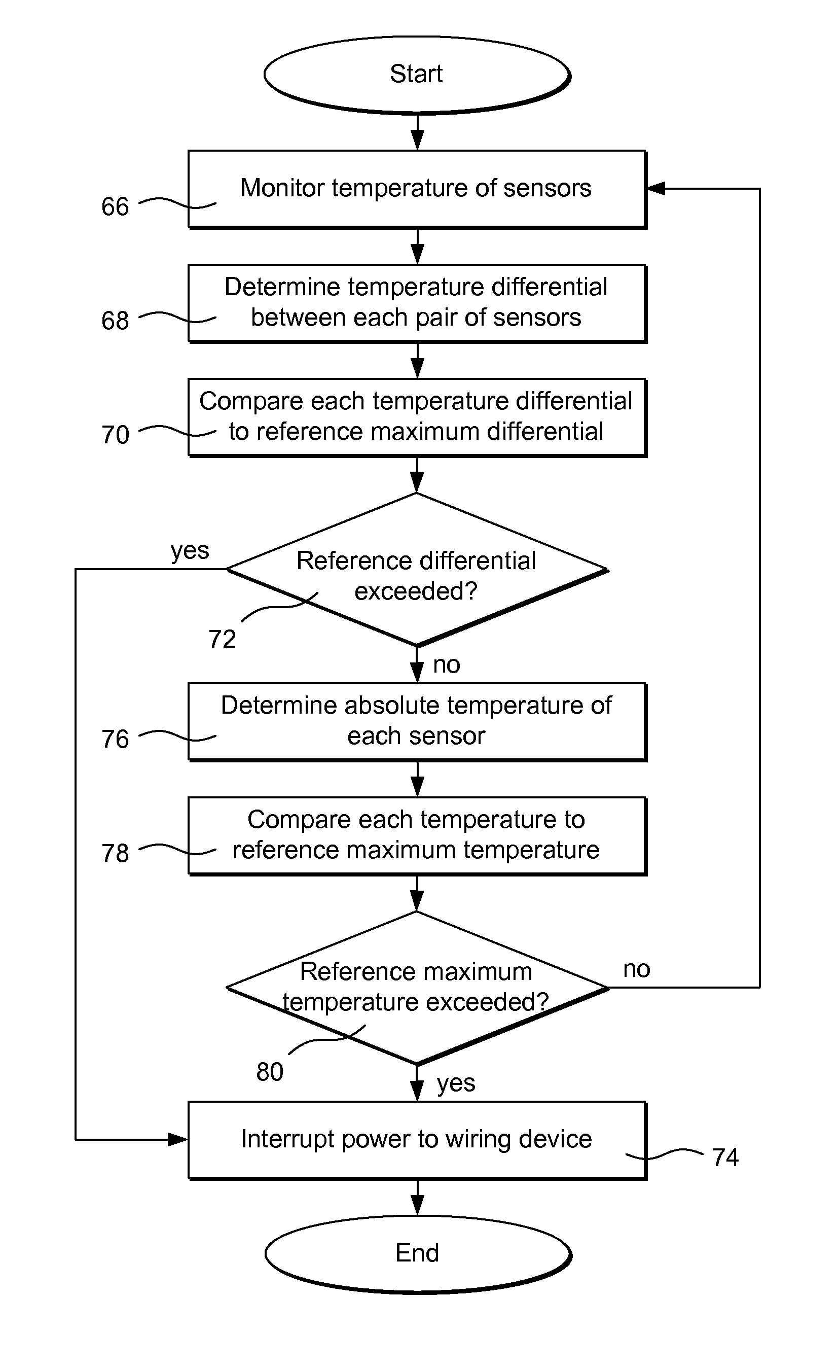
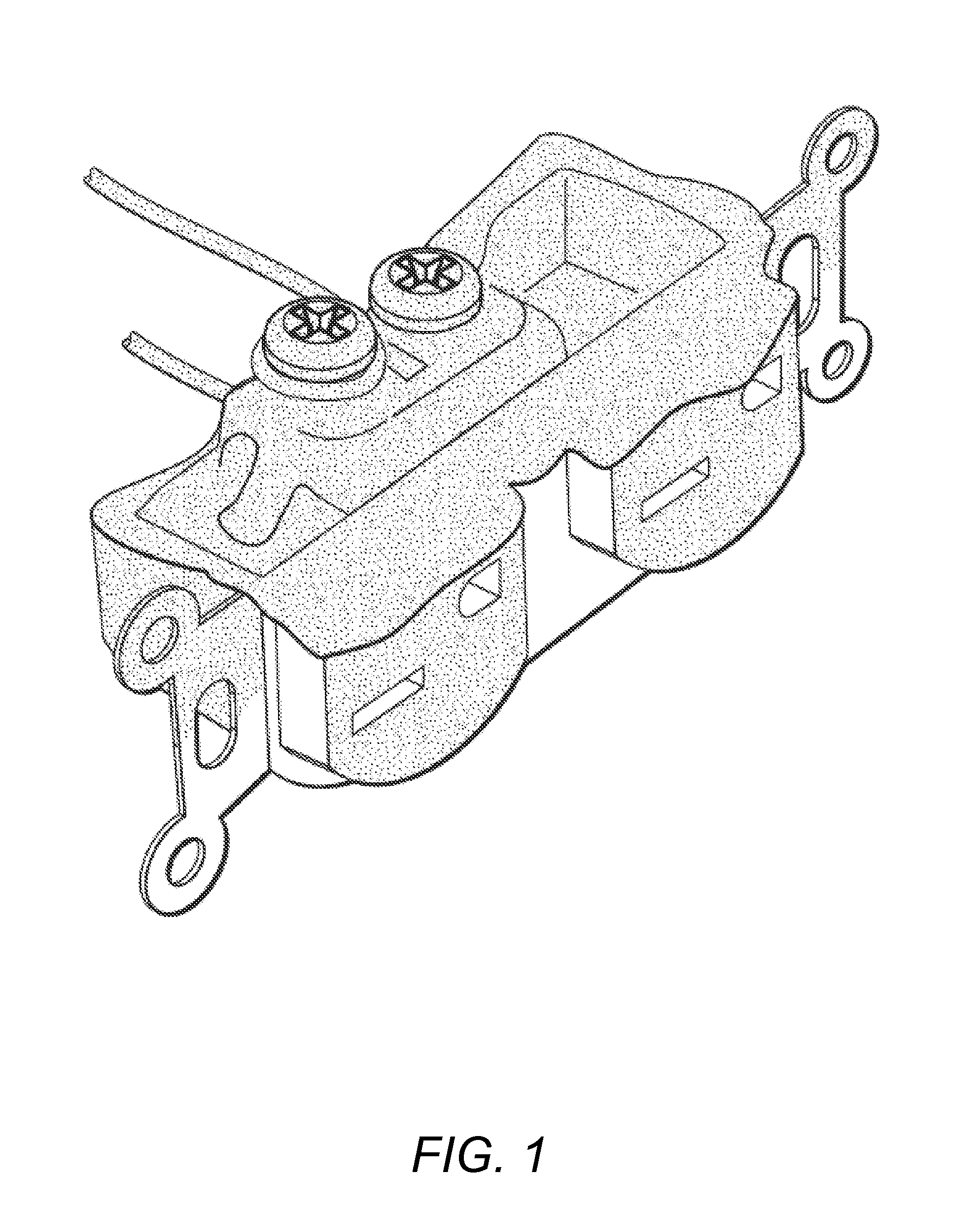
[0029]Embodiments of the invention provide improved detection of series fault conditions, and provide improved response possibilities upon detection of such conditions. Some embodiments of the invention utilize electronic temperature sensors such as solid-state sensors and temperature sensors integrated into an integrated circuit. In some embodiments, the electronic temperature sensors are connected to a printed circuit board (PCB) that is connected to supply wire connectors, and in other embodiments they are directly connected to supply wire connectors. In some embodiments, differential temperature sensing, as an alternative to or ...


PUM


Abstract

Systems and methods that provide improved detection of series fault and other localized unsafe heating conditions are described. The systems and methods provide an increased range of response possibilities upon detection of such conditions. Multiple temperature sensors are located in close proximity with the location of potential over-heating events, and differential temperature sensing is used to detect over-heating events. Electronic sensors in accordance with implementations of the present invention detect overheating conditions at lower temperatures and more quickly because of the close proximity of the sensors to locations of potential overheating and because of the differential temperature sensing, thereby improving the safety of electrical wiring devices and fixtures.

Description

CROSS-REFERENCE TO RELATED APPLICATIONS[0001]This application is a continuation-in-part of prior application Ser. No. 12 / 236,400, filed Sep. 23, 2008.BACKGROUND OF THE INVENTION[0002]1. Field of the Invention[0003]The present invention relates to electrical fixtures and wiring devices, and more particularly to systems and methods for detecting unsafe thermal conditions in fixtures and wiring devices.[0004]2. Background and Related Art[0005]Many building fires occur because of unsafe heating associated with power outlets, light switches or other fixture. For example, loose connections cause points of excessive heating under normal use. If not detected, this localized heating leads to fires by igniting wire insulation, fixture materials, framing, or other nearby flammable objects. The fires caused by the excessive localized heating result in property loss, injury and even death.[0006]These points of excessive heating are most commonly found at the wiring connection to the fixture, but...

Claims


Application Information

Patent Timeline
IPC IPC(8): H02H5/04
CPCG08B17/06
Inventor BAXTER, MICHAELSPACHT, GLENN
Owner ENERGY SAFE TECH
Features
  • Generate Ideas
  • Intellectual Property
  • Life Sciences
  • Materials
  • Tech Scout
  • Unparalleled Data Quality
  • Higher Quality Content
  • 60% Fewer Hallucinations
Learn More