Line-of-sight optical detection system, and communication system

a communication system and optical detection technology, applied in the field of line-of-sight optical detection system, can solve the problems of light cost, add to the cost of the detection system, light source and light detector, etc., and achieve the effect of relatively low cost of the communication system

Inactive Publication Date: 2010-03-25
KONINKLIJKE PHILIPS ELECTRONICS NV
View PDF10 Cites 17 Cited by
  • Summary
  • Abstract
  • Description
  • Claims
  • Application Information

AI Technical Summary

Benefits of technology

[0025]In a particularly preferred embodiment, the light sources are part of a normal lighting infrastructure, i.e. the light sources operate as illumination light sources. Inside buildings, but also outdoors, spaces (rooms, roads) may be illuminated by a plurality of dimmable LEDs. Dimming of an LED is not done by reducing the LED current but by regularly interrupting the LED current; these interruptions can be patterned to form a code. Since CDMA is a known per se coding principle, a further elaboration is not needed here. An important advantage of using the LEDs of a normal lighting infrastructure is, on the one hand, that existing infrastructure can be used so that it is not necessary to install new LEDs, and on the other hand that the costs of such infrastructure does not only bear on the communication system but also (primarily) bears on the illumination purpose, which is needed anyway, so that the costs of the communication system are relatively low. Further advantageous elaborations are mentioned in the dependent claims.

Problems solved by technology

One basic disadvantage is that the light source and the light detector are dedicated instruments, used for their task in the detection system only.
This means that the costs of light source and light detector have their justification in the detection system only, in other words it adds to the costs of the detection system.
Another basic disadvantage is that the detection system is only capable of performing a one-dimensional detection without position resolution along this one dimension.
A further consequence is that such detection system is not capable of measuring the size of the obstruction: does it see a man or a mouse?
Likewise, for use in a traffic counting system, when a light source and light detector are located at opposite sides of the road, it is possible to detect the passing of a vehicle by detecting a brief interruption of the received light, but it is not possible to distinguish between two lanes, and if two (or more) vehicles are passing simultaneously in different lanes, they will be detected and counted as one.
Similarly, for use in a detection system for detecting atmospheric conditions, it may be that the detected light level is reduced due to contamination of the light source or the light detector, which may then erroneously be interpreted as fog.
If it is desirable to reduce, for the system as a whole, the above-mentioned disadvantage of one-dimensional detection capability without position resolution along this one dimension, the system as a whole would require multiple source / detector sets, further increasing the costs of the system.

Method used


Image

  • Line-of-sight optical detection system, and communication system
  • Line-of-sight optical detection system, and communication system
  • Line-of-sight optical detection system, and communication system

Examples


Embodiment Construction

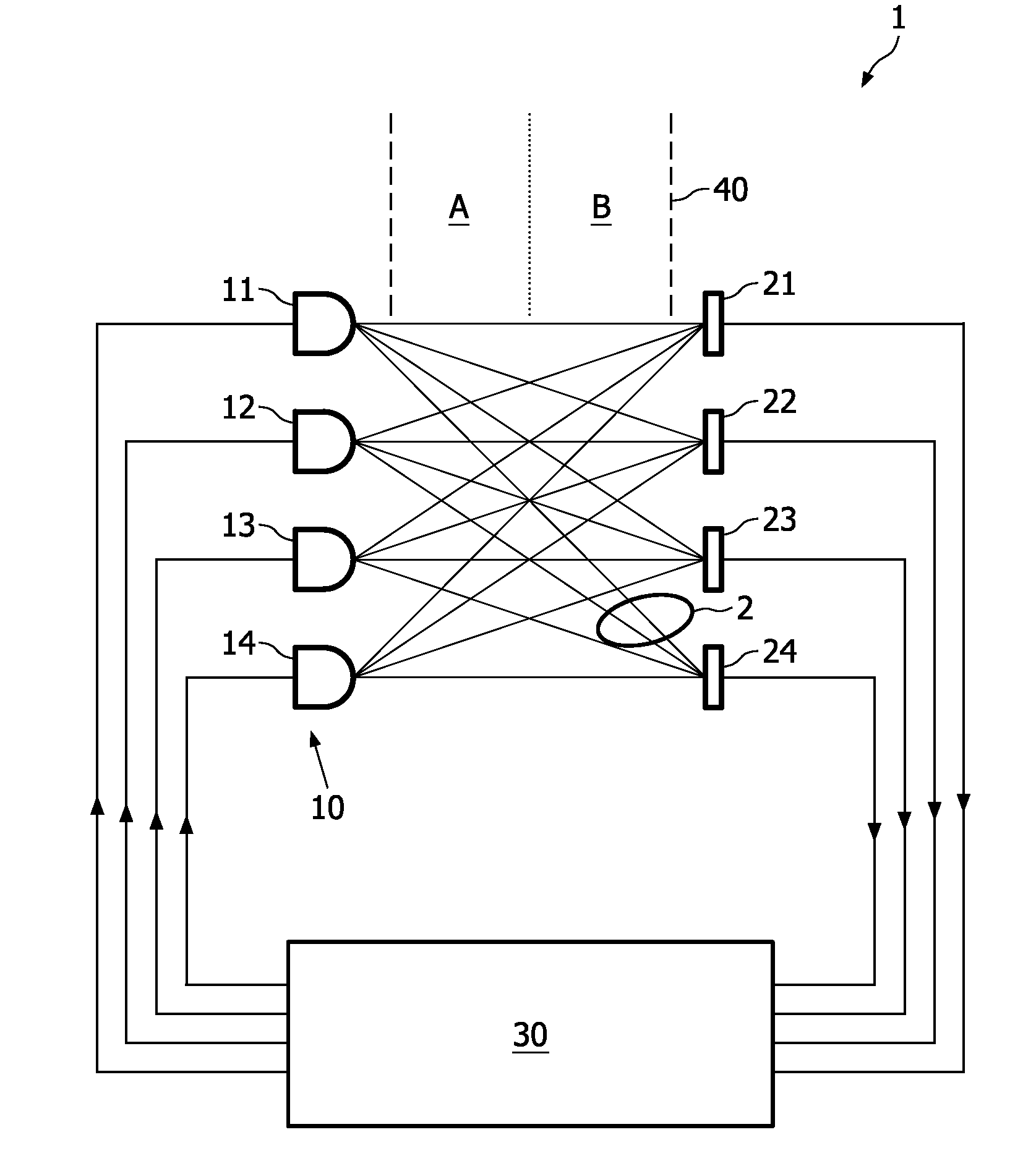
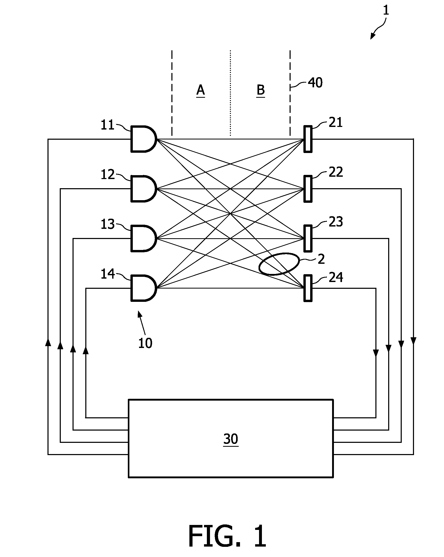
[0029]FIG. 1 schematically shows a line-of-sight optical detection system 1. This system 1 comprises a plurality of LEDs 11, 12, 13, 14; the number of LEDs shown in FIG. 1 is equal to four, but the system may have a different number of LEDs. The system further comprises a plurality of light detectors 21, 22, 23, 24, suitably phototransistors; the number of detectors shown in FIG. 1 is equal to four, but the system may have a different number of detectors. The detectors have their outputs coupled to a controller 30, which may be a suitably programmed microprocessor, for instance.

[0030]The LEDs are part of an illumination system 10 for illuminating a room, under control of the controller 30, which controls the LEDs such that they emit CDMA encoded light. Each LED is coded in a different way. Particularly, each LED emits an identification code. The physical positioning of the LEDs may be regular or irregular; in the figure, they are lined up at regular intervals, but this is not essent...


PUM


Abstract

A line-of-sight optical detection system comprises: a plurality of dimmable light sources (11, 12, 13, 14); a controller (30) for controlling the light sources to emit coded light; a detector (21, 22, 23, 24), receiving light from two or more of said light sources. The controller decodes the detector output signal, determines which light source contributes to the light received by the detector and, on the basis of the outcome, determines a location of an object (2). A communication system (100) comprises:—a plurality of dimmable light sources (111, 112, 113, 114); a controller (130) for controlling the light sources to emit coded light; a receiver (200) comprising a CPU (230) and a light detector (211), receiving light from at least one of said light sources. The CPU (230) decodes the detector output signal and, on the basis of the outcome, decides on an action to be taken.

Description

FIELD OF THE INVENTION[0001]The present invention relates in general to a line-of-sight optical detection system, particularly for detecting the presence of objects, animals or people, more particularly capable of detecting the position of detected objects, animals or people.[0002]The present invention also relates in general to a communication system, for sending personalized messages to a person or apparatus or receiving personalized messages from a person or apparatus.BACKGROUND OF THE INVENTION[0003]In many applications, it is desirable to have a detection system that is capable of detecting the position of objects, animals or people.[0004]For instance, particularly inside a building but also outdoors, an intrusion detection system may be desirable, capable of detecting the presence of an object, animal or person, capable of detecting the position of such object, animal or person, capable of tracking such object, animal or person, and perhaps even capable of measuring the size o...

Claims


Application Information

Patent Timeline
Patent Type & Authority Applications(United States)
IPC IPC(8): H04J14/00H04B10/112H04B10/114H04B10/116
CPCG01V8/20G08B5/006H04B10/116H04B10/1125H04B10/1149G08B13/183
Inventor DAMINK, PAULUS HENRICUS ANTONIUSCOLAK, SEL BRIANFERI, LORENZOPENNING DE VRIES, HENDRICUS THEODORUS GERARDUS MARIA
Owner KONINKLIJKE PHILIPS ELECTRONICS NV
Why Eureka
Try Eureka