Eureka AIR delivers breakthrough ideas for toughest innovation challenges, trusted by R&D personnel around the world.

Pipeline Protection and Levee Module System

Active Publication Date: 2010-03-25
BOUDREAUX JR JAMES C
View PDF25 Cites 14 Cited by
  • Summary
  • Abstract
  • Description
  • Claims
  • Application Information

AI Technical Summary

Benefits of technology

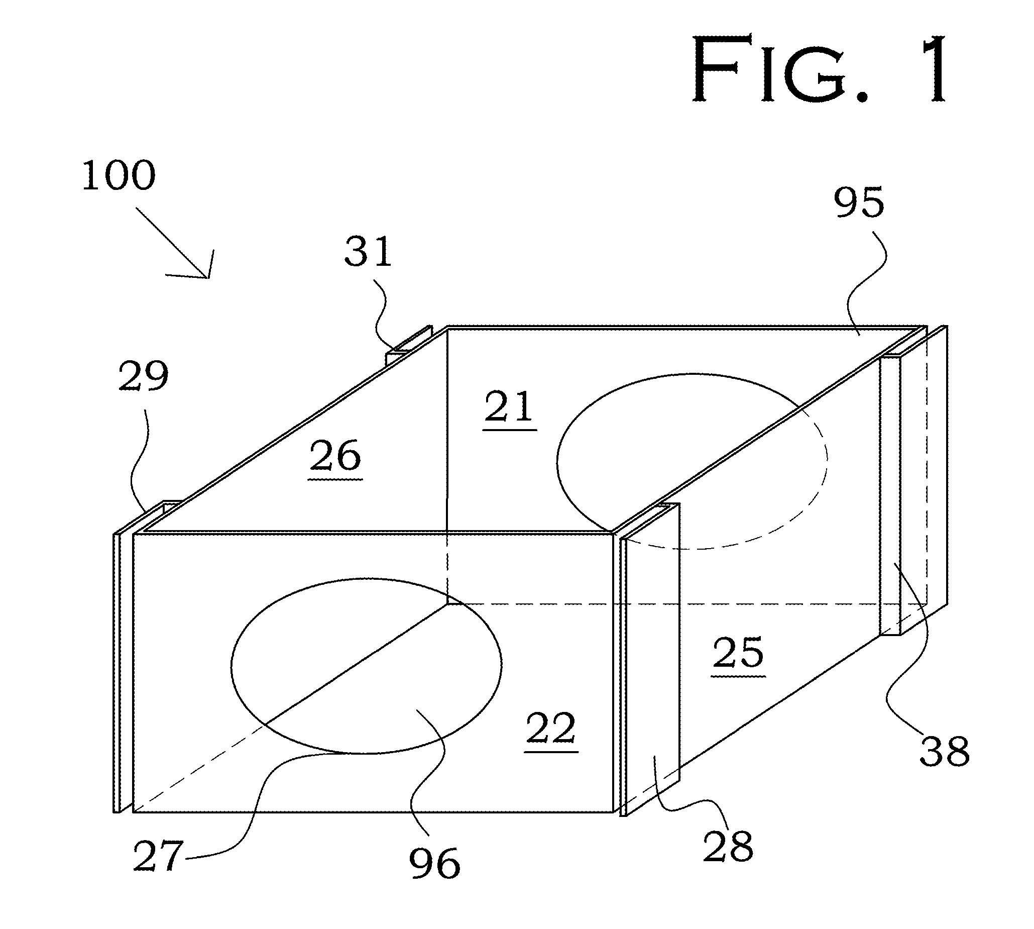
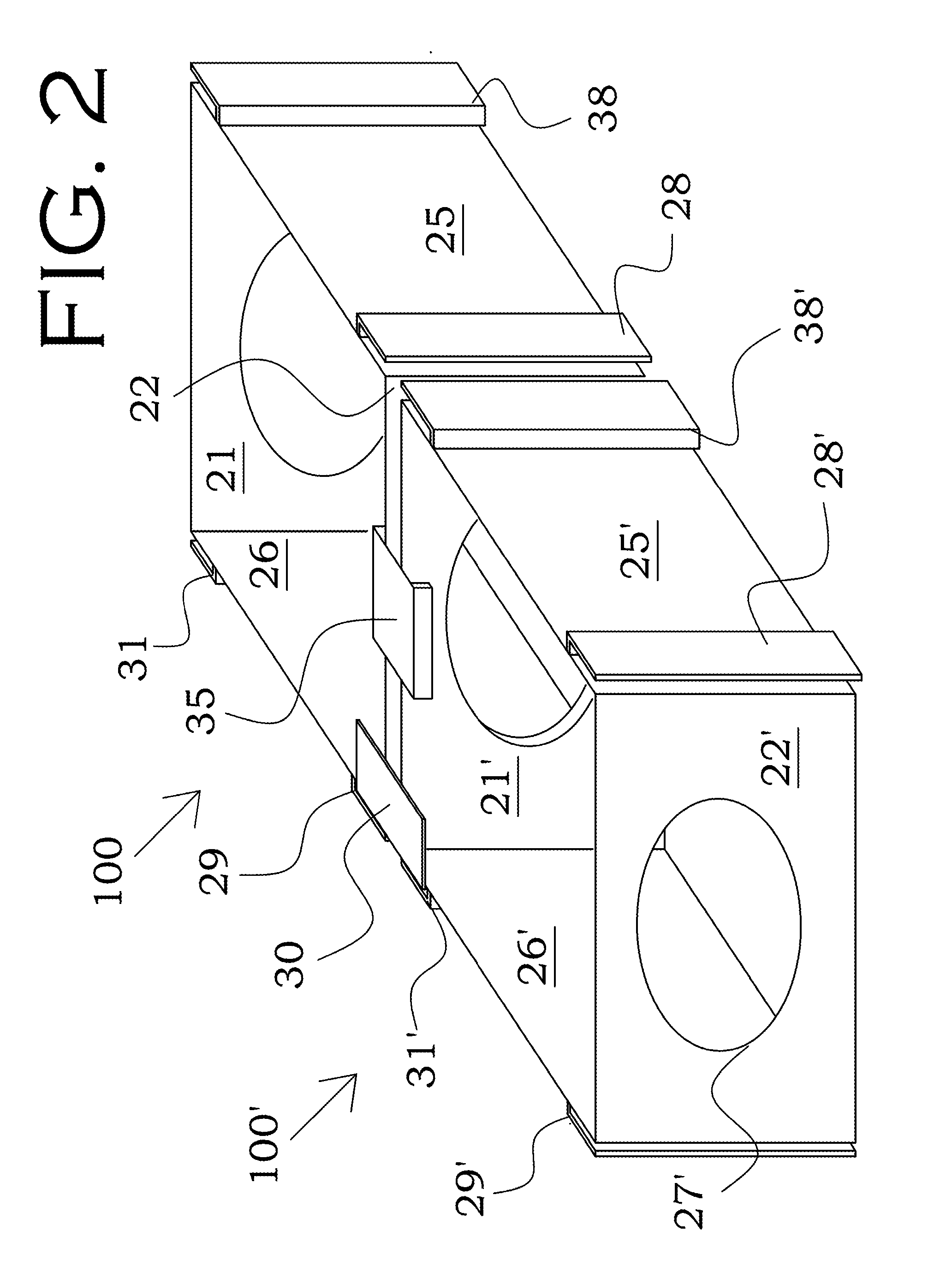
[0008]The present invention is directed to a levee and barrier module and system that is capable of providing fluid control and containment and that is capable of providing pipeline protection and pipeline integration into levees. The levee and barrier module includes an outer module shell and a module-to-module connection system to connect adjacent outer shells. The outer module shell, being in the general shape of a prism or prism with attached cylindrical section or sections, comprises two opposing end walls and at least two opposing side walls, and is configured to enclose or support filler material. The two opposing end walls are configured with end apertures. The out

Problems solved by technology

Floods can have a devastating effect, both in economic loses and in lives disrupted or lost.
Numerous attempts have been made to solve the water containment and control problem, yet each solution is deficient in some area.
While earthen levees are economical to install, the motion of the water causes rapid deterioration, as the levee has no structure or armor to protect it.
Also, particularly in some soils, subsidence reduces the height of the levee over time.
Because of subsidence and because of damage due to water and wave action, the initial financial investment vanishes as the earthen levee deteriorates over a period of a few years.
Also, as there is no structure beneath the soil, during floods the soil beneath the foundation of the levee may weaken or even form a liquefied zone, undermining the stability of the levee.
Furthermore, an earthen levee cannot be easily built while in a flood, emergency, or repair situation.
For example, if a l

Method used


Image

  • Pipeline Protection and Levee Module System
  • Pipeline Protection and Levee Module System
  • Pipeline Protection and Levee Module System

Examples


second embodiment

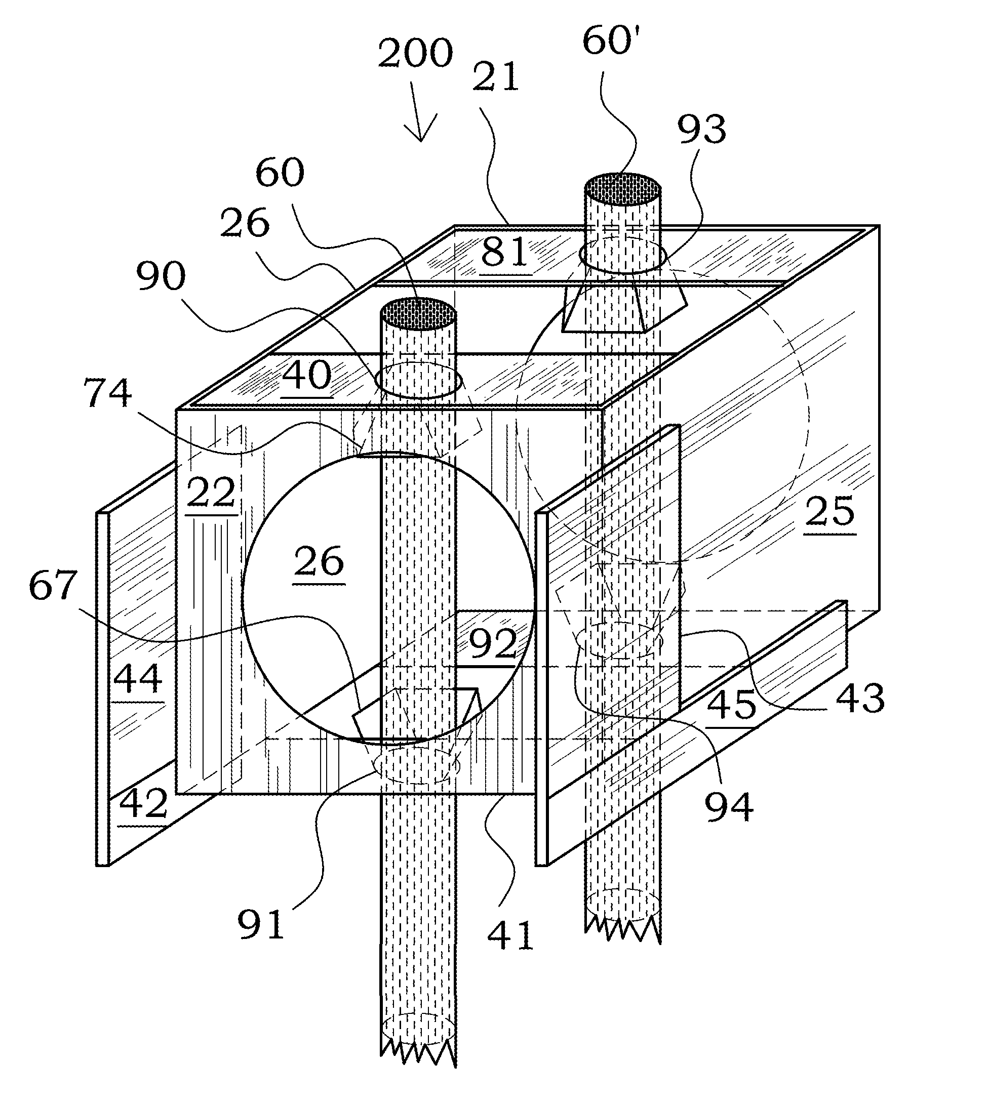
[0073]Referring now to FIG. 6, FIG. 7, and FIG. 8, a levee and barrier module, shown generally as reference number 200, is illustrated in accordance with the second exemplary embodiment of the present invention. The levee and barrier module 200 of the second embodiment comprises the outer shell formed of side walls 25, 26 and end walls 21, 22, with a second module-to-module connecting system used to connect horizontally and vertically adjacent levee and barrier modules 200. Module 200 is useful for construction of a levee or barrier system either above or below the level of the water.

[0074]This second connecting system includes a substantially vertical lateral projection 43, a substantially vertical lateral projection 44, a substantially vertical lower projection 45, and a substantially vertical lower projection 42. Lower projection 45 is a panel somewhat shorter in length than side wall 25 and can be attached to—or integrally formed with—the lower edge of side wall 25, extending so...

third embodiment

[0097]The top view of FIG. 11 illustrates not only the third module-to-module connection type, but also the additional feature of top end guide plates 40, 81 with conduits 90, 93 plus top side guide plates 83, 89 added to the basic module of FIG. 10. The opposing bottom guide plates, not shown, are also provided.

[0098]FIG. 11 additionally illustrates the additional optional feature of a cornering module-to-module connection system. In constructing a levee, at times there is a need to construct a substantially 90-degree corner. Additional complementary flanges 334 and 333 can be installed on the side walls 25 or 26. Complementary flanges 334 and 333 can interconnect with flanges on a 90 degree offset module 300″, to provide for a 90-degree angle corner.

[0099]Referring now to FIG. 12 and FIG. 13, a levee and barrier module, shown generally as reference number 400, is illustrated in accordance with the fourth embodiment of the present invention. The fourth embodiment provides a collaps...

fourth embodiment

[0102]An additional system of application of the collapsible module of the fourth embodiment is the utilization of side partition 410 and side partition 415 to extend the levee and barrier module system over a pipeline. Partition 410 and side partition 415 can be configured to be somewhat reduced in height (not shown) to allow space for the pipeline to run under them. The reduction in height would be to a dimension determined by the pipeline structure that side partition 410 and side partition 415 will be passing over. Because side partition 410, and side partition 415 are smaller and lighter and move freely up and down, they would provide structure to the levee and barrier module system, but would not deform or damage the pipeline positioned under them. Additional support could be provided below the pipeline, as desired. Optionally, side partition 410 and side partition 415 can extend between two full size modules (such as the full size module illustrated in FIG. 11) instead of ext...


PUM


Abstract

A levee and barrier module for fluid control and containment is provided including an outer module shell and a module-to-module connection system to attach adjacent outer shells. The outer module shell is formed by opposing side walls and two opposing end walls and is configured to enclose or support filler material. The outer module shell defines a top aperture and a bottom aperture. The bottom aperture allows filler material communication with the earth below the module. The top aperture allows filler material to be added to the module, as well as visual observation of, and maintenance of, the amount of contained filler material. A presented application is directed to protecting pipelines and to allowing pipeline integration or association with levees.

Description

CROSS-REFERENCE TO RELATED APPLICATIONS[0001]This application is a Continuation-in-Part of co-pending application Ser. No. 11 / 603,365, filed 11-21-2006, which claims the benefit of U.S. Provisional Application No. 60 / 739,475, filed Nov. 22, 2005, and U.S. Provisional Patent Application No. 60 / 813,885, filed Jun. 12, 2006; all cited prior applications are incorporated by reference in this application.FIELD OF THE INVENTION[0002]This invention relates generally to modular units for construction of levee and barriers, with a particular application to pipeline protection.DESCRIPTION OF THE PRIOR ART[0003]Floods can have a devastating effect, both in economic loses and in lives disrupted or lost. Numerous attempts have been made to solve the water containment and control problem, yet each solution is deficient in some area.[0004]The most common solution for water control problems involves the use of earthen embankments or levees made of soil. While earthen levees are economical to instal...

Claims


Application Information

Patent Timeline
IPC IPC(8): E02B7/16E02D5/60E02D5/52
CPCE02B3/108
Inventor BOUDREAUX, JR., JAMES C.
Owner BOUDREAUX JR JAMES C
Why Eureka
Eureka Blog
Learn More