Flash Drive With Spring-Loaded Swivel Connector

a technology of flash memory and spring-loaded swivel connectors, which is applied in the direction of coupling device details, coupling device connection, instruments, etc., can solve the problems of flash memory access slowness, flash memory sector life span limitation, and inherent limitations of flash memory, so as to reduce wear and ensure transport.

Inactive Publication Date: 2010-03-25
SUPER TALENT TECH CORP
View PDF99 Cites 110 Cited by
  • Summary
  • Abstract
  • Description
  • Claims
  • Application Information

AI Technical Summary

Benefits of technology

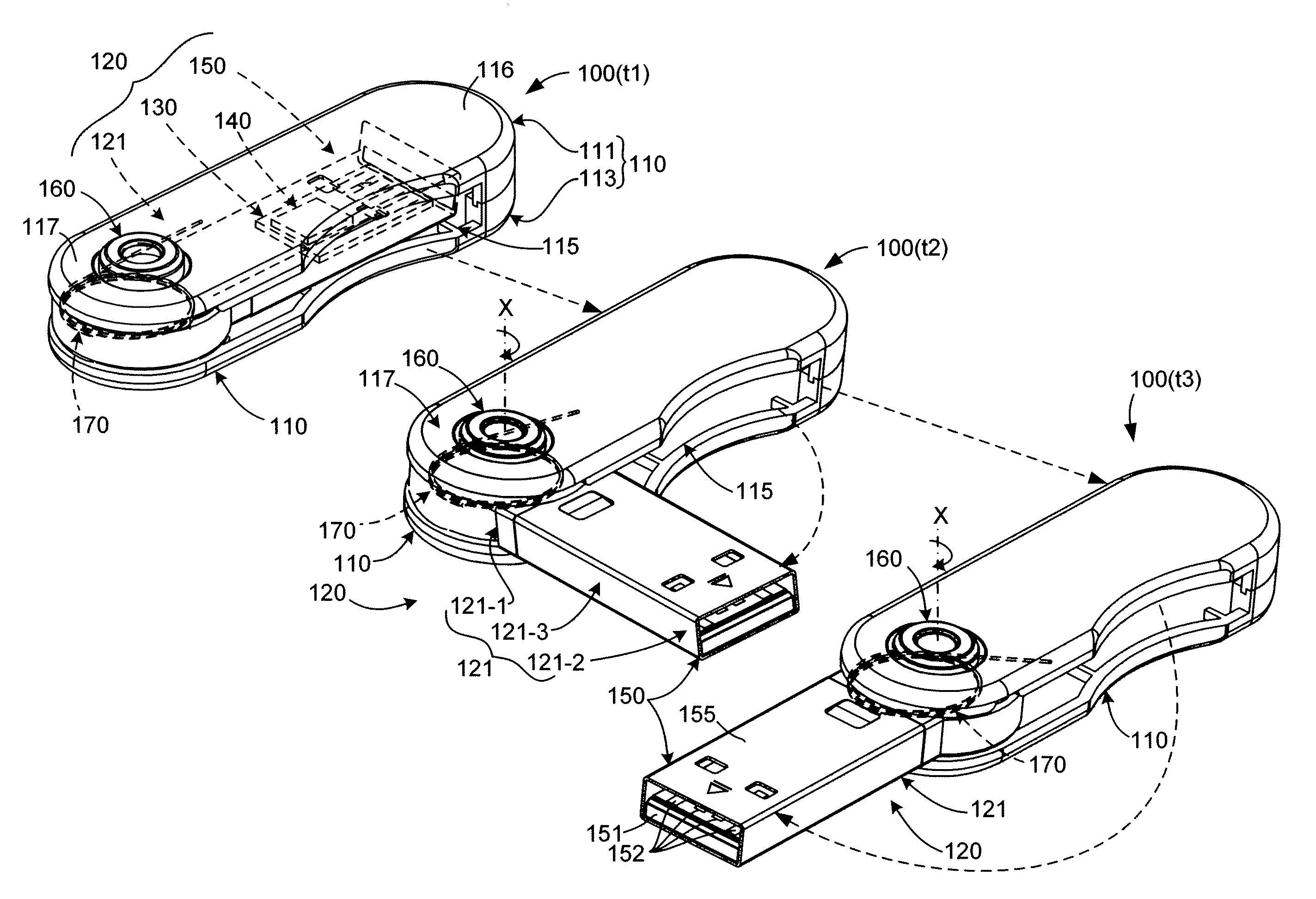
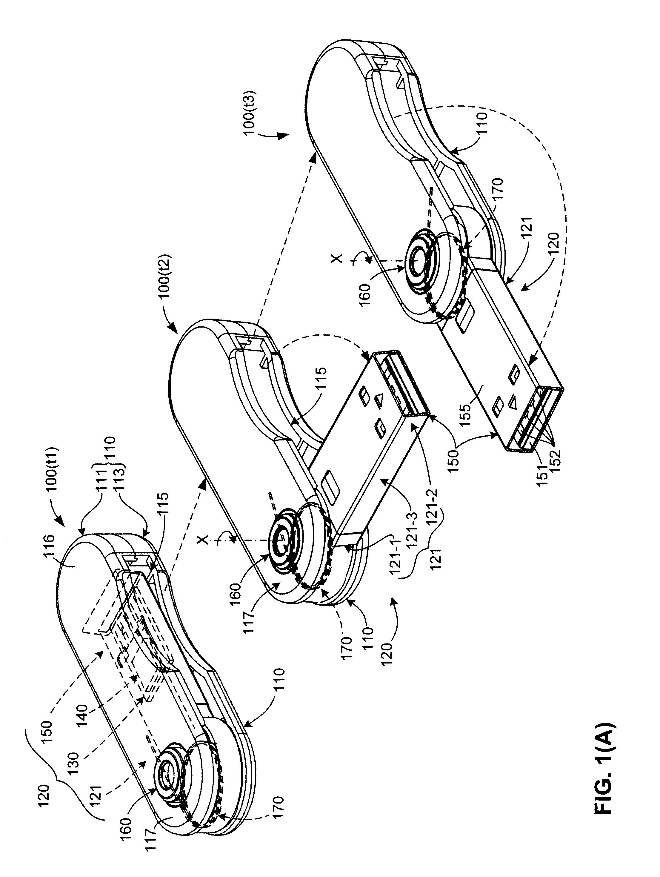
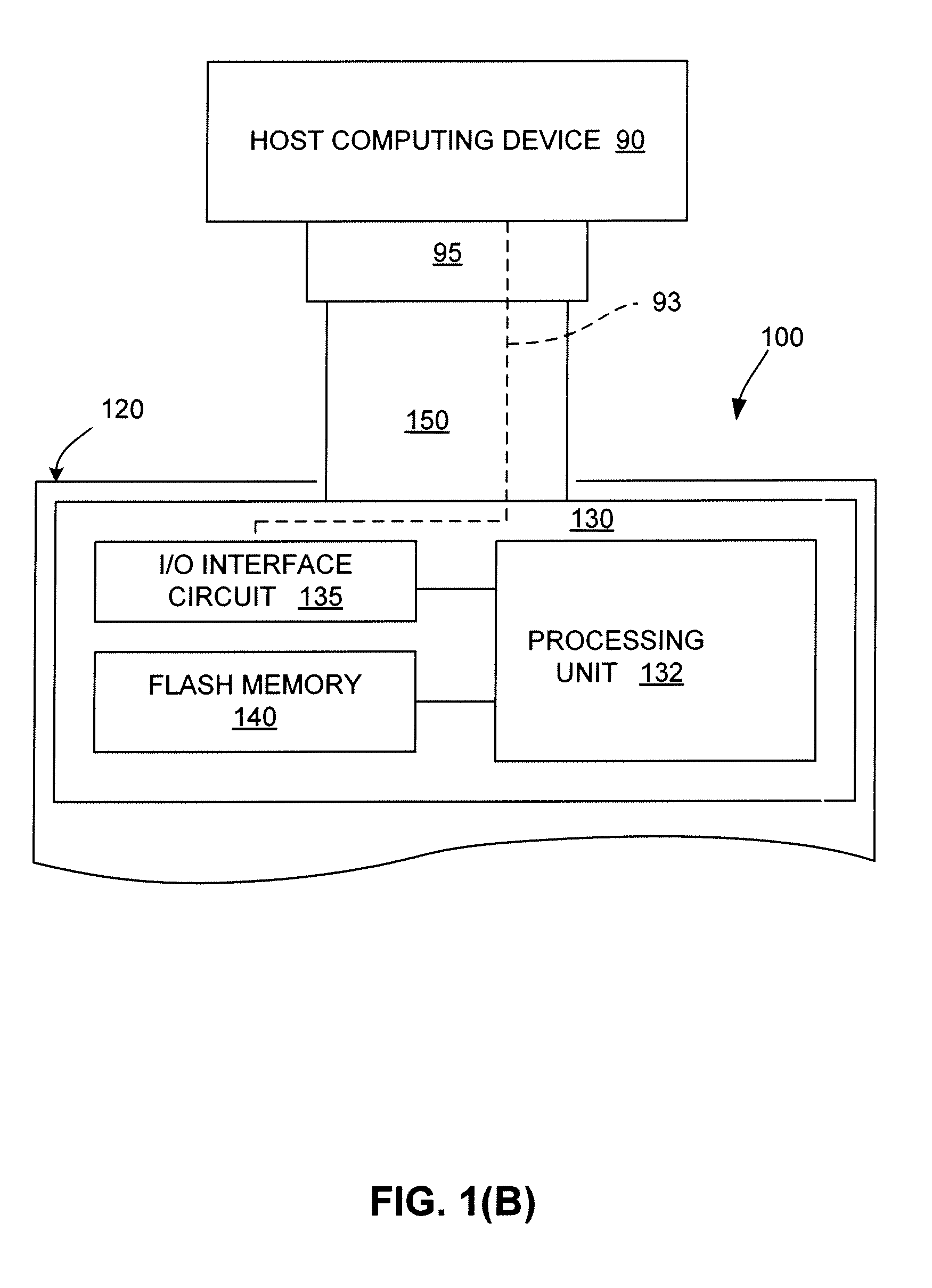
[0016]The present invention is particularly directed to a swivel-type portable computer peripheral device (apparatus) for safely transporting a MLC based flash memory chip (device) in which a plug connector (e.g., a USB plug connector) is electrically connected to the MLC based flash memory device and is mounted on a swivel rack assembly that is pivotable (swivelable) between a retracted position inside a housing and a deployed position outside the housing through a side opening defined by the housing by way of a torsion spring (resilient torsion member) that biases the swivel rack assembly either into or out of the housing. A locking mechanism is provided to secure the swivel rack assembly in the retracted and deployed positions. The torsion spring, which is preferably a coil wire spring, is coupled to one of the swivel rack assembly and at its other end to the housing. In a spring-loaded extension embodiment, the torsion spring acts to bias the swivel rack assembly from the retracted position to the deployed position upon de-activation of the locking mechanism. Conversely, in a spring-loaded retraction embodiment, the torsion spring acts to bias the swivel rack assembly from the deployed position to the retracted position upon de-activation of the locking mechanism. By utilizing torsion springs to retract or deploy the plug connector in this manner, the present invention provides a computer peripheral device having a desirable spring-loaded deploying / retracting feature that protects the plug connector without the need for a separate cap, and also serves to reduce wear that can lead to jamming by maintaining the plug connector in a proper orientation relative to the housing during the deploying and retracting operation.

Problems solved by technology

As such, a problem arises when mobile systems that are designed for one type of flash memory are constructed using another, incompatible type of flash memory.
In addition to the limitations introduced by the USB standard, there are inherent limitations with flash memory.
Also, flash memory sectors have a limited life span; i.e., they can be erased only a limited number of times before failure.
Accordingly, flash memory access is slow due to the erase-before-write nature and ongoing erasing will damage the flash memory sectors over time.
However, there are a number of problems associated with the MLC flash memory.
First, the MLC flash memory has a low reliability.
Secondly, the MLC flash memory data programming rules require writing to an ascending page in the same block or writing to a blank new page if there are data existed in the original page.
This creates a huge problem not only to the cost, but also to the physical size of the flash memory device.
Furthermore, the traditional usage of the flash memory devices is generally in a very clean and relatively mild environment, thus the packaging design such as enclosure of the flash memory device is not suitable for hostile environment such as military and heavy industrial applications.
A problem with convention pen-type peripheral devices is that the removable cover can become inadvertently lost while the device is in use, thereby leaving the USB plug connector exposed to damage or contamination.
Although “press-push” memory devices avoid the problems of conventional pen-type peripheral devices, e.g., by avoiding the need for a separate cap, the molded plastic used to produce these devices can become worn over a relatively short amount of time, leading to undesirable resistance or jamming that prevents the desired retraction of the connector when not in use.

Method used


Image

  • Flash Drive With Spring-Loaded Swivel Connector
  • Flash Drive With Spring-Loaded Swivel Connector
  • Flash Drive With Spring-Loaded Swivel Connector

Examples


Embodiment Construction

[0045]The present invention relates to an improvement in flash memory devices such as USB flash drives. The following description is presented to enable one of ordinary skill in the art to make and use the invention as provided in the context of a particular application and its requirements. As used herein, directional terms such as “upper”, “upwards”, “lower”, “downward”, “front”, “rear”, and “side” are intended to provide relative positions for purposes of description, and are not intended to designate an absolute frame of reference. In addition, the phrases “integrally connected” and “integrally molded” is used herein to describe the connective relationship between two portions of a single molded or machined structure, and are distinguished from the terms “connected” or “coupled” (without the modifier “integrally”), which indicates two separate structures that are joined by way of, for example, adhesive, fastener, clip, or movable joint. Various modifications to the preferred emb...


PUM


Abstract

A swivel-type computer peripheral device includes a housing and a swivel rack assembly that swivels relative to the housing between a retracted position, in which a PCBA having a plug connector mounted on the swivel rack assembly is disposed inside the housing, and a deployed position, in which the swivel rack assembly is rotated outside of the housing such that the plug connector is positioned for insertion into a host computer socket. A torsion spring is connected between the housing and the swivel rack assembly and arranged to bias the swivel rack assembly either into the deployed position or into the retracted position. A locking mechanism controlled by a push button or another actuating mechanism is used to selectively lock the swinging rack in a retracted position and a deployed position.

Description

RELATED APPLICATIONS[0001]This application is a continuation-in-part (CIP) of co-pending U.S. patent application for “Flash Drive With Spring-Loaded Retractable Connector”, Ser. No. 12 / 361,772, filed Jan. 29, 2009.[0002]This application is also a (CIP) of co-pending U.S. patent application for “Universal Serial Bus (USB) Flash Drive Having Locking Pins and Locking Grooves for Locking Swivel Cap”, Ser. No. 11 / 929,857, filed Oct. 30, 2007.BACKGROUND OF THE INVENTION[0003]1. Field of the Invention[0004]The invention relates to flash memory devices, more particularly to systems and methods of managing memory addresses in a large capacity multi-level cell (MLC) based flash memory device.[0005]2. Description of the Related Art[0006]As flash memory technology becomes more advanced, flash memory is replacing traditional magnetic disks as storage media for mobile systems. Flash memory has significant advantages over floppy disks or magnetic hard disks such as having high-G resistance and low...

Claims


Application Information

Patent Timeline
Patent Type & Authority Applications(United States)
IPC IPC(8): H01R13/44G06F13/20
CPCG06K19/07732G06K19/07743G11C2211/5641G11C16/0408G11C16/10G11C11/5621
Inventor NI, JIM CHIN-NANMA, ABRAHAM C.
Owner SUPER TALENT TECH CORP
Why Eureka
Try Eureka