
Minimally-thick orthopedic prosthesis is disclosed which closely matches the end of a bone of a joint after that bone end has been minimally reshaped and resurfaced by an orbital or lineally oscillating orthopedic resurfacing tool in the minimally invasive orthopedic surgical repair or reconstruction of hip, knee, ankle, shoulder, elbow, wrist, and other joints

a technology of orthopedic prosthesis and bone end, which is applied in the field of minimally-thick orthopedic prosthesis, can solve the problems of secondary surgical repair procedures, blood clots and heart attacks, and may be difficult to achieve, and achieve the effects of less time in surgery and less cost of surgical procedures, and more uniform and satisfactory recovery from surgery

Inactive Publication Date: 2010-03-25
HATCH EDWIN BURTON
View PDF17 Cites 150 Cited by
  • Summary
  • Abstract
  • Description
  • Claims
  • Application Information

AI Technical Summary

Benefits of technology

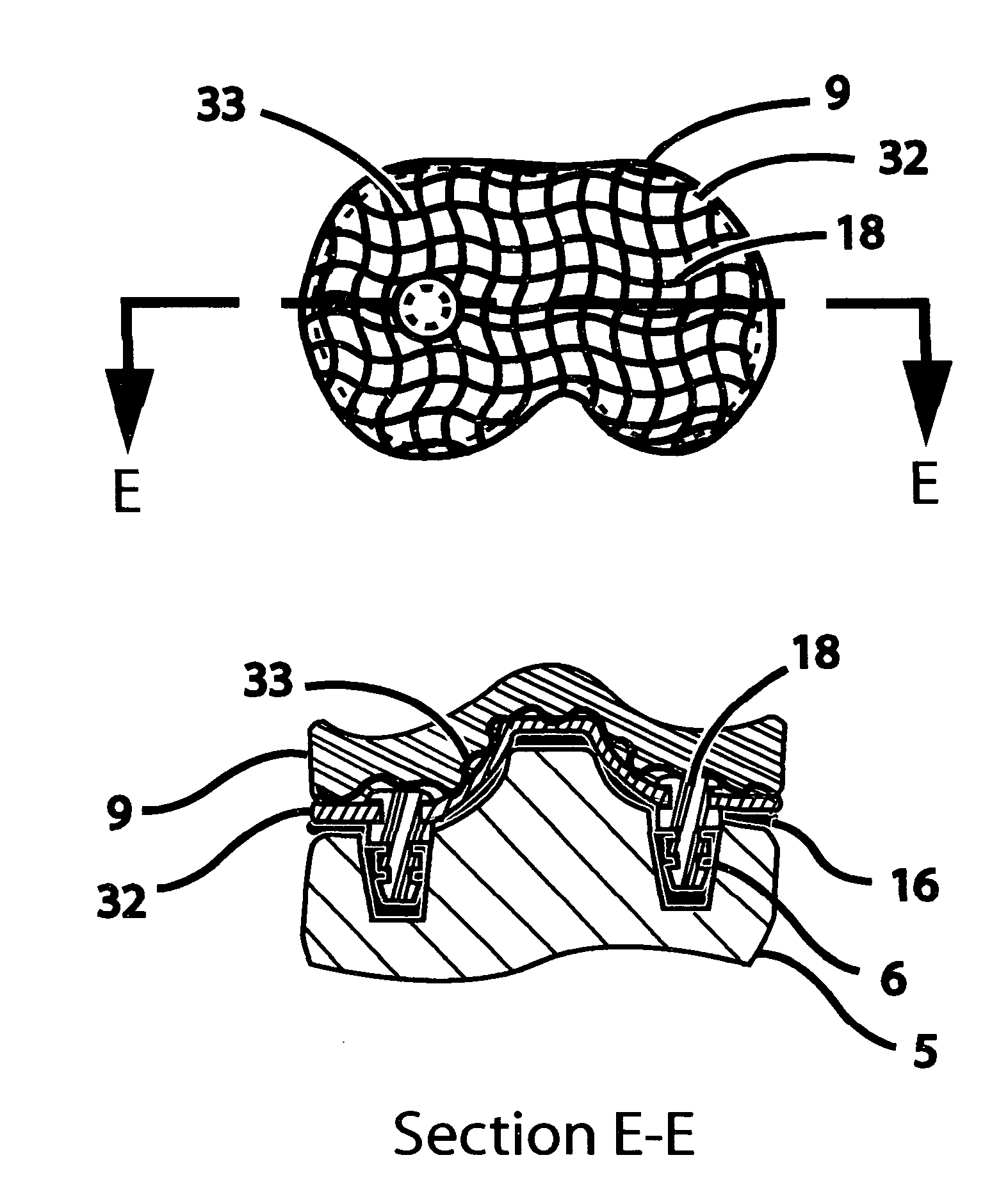
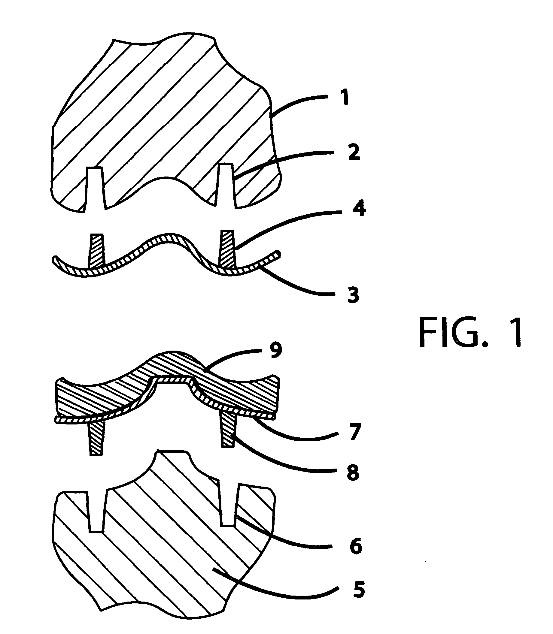
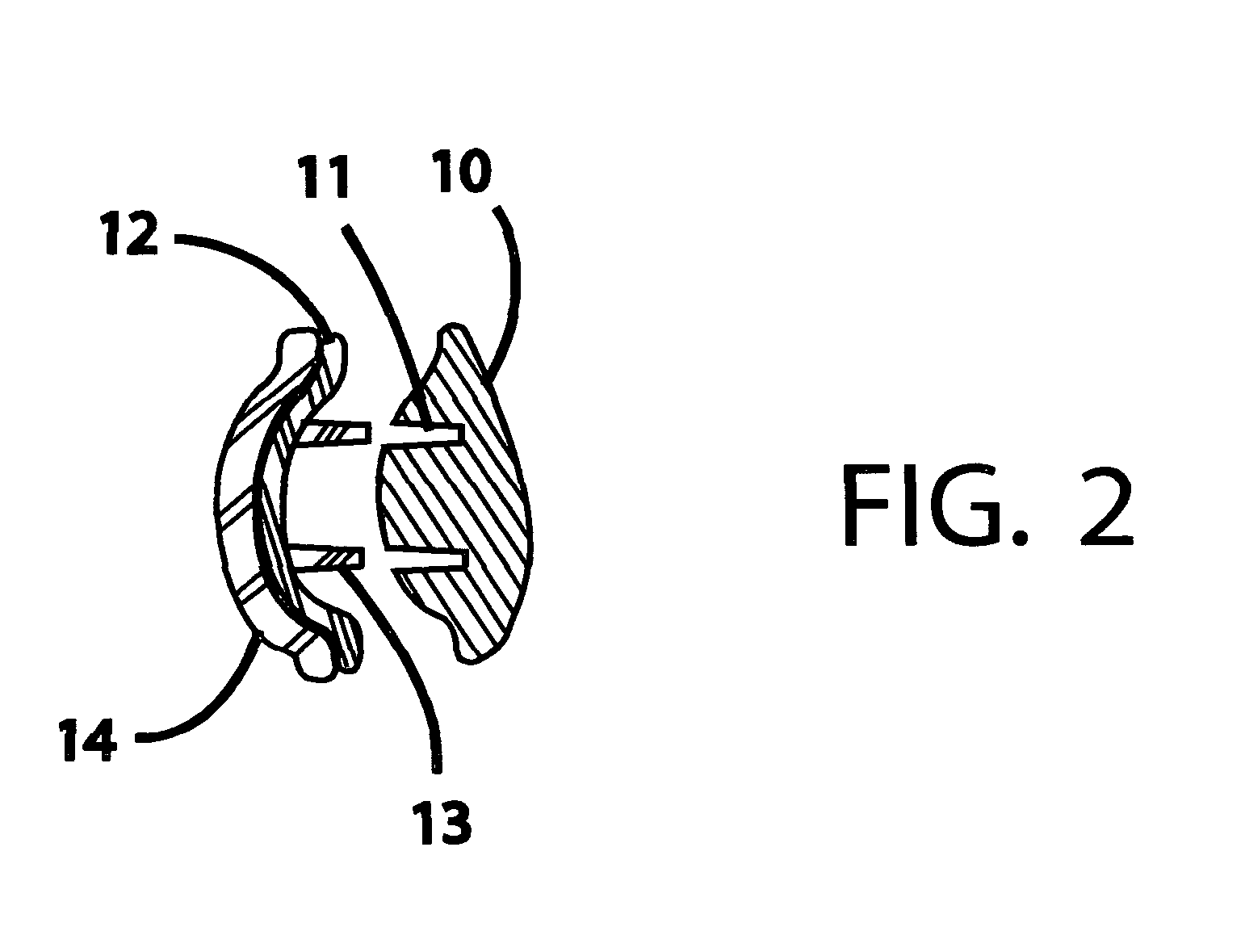
[0006]This minimally-thick surface-matching prosthesis construction is a radical departure from the massive-cast-knuckle type of prosthesis as is typically used in total knee replacement surgery. In this orthopedic surgical repair or reconstruction of the hip, knee, ankle, shoulder, elbow, wrist, or other joint, an orbital or lineally oscillating orthopedic resurfacing tool is used which has a culling head so configured as to match an average typical shape of the surface of a particular bone end. A minimally-thick orthopedic prosthesis is created which closely matches the surface of the orthopedic resurfacing tool's cutting head and therefore closely matches the surface of the bone end resurfaced by that cutting head. This minimally-thick surface-matching prosthesis is mounted onto the resurfaced bone end with mechanical attachments and using bone glue both as a bonding agent and to fill the space between the minimally-thick surface-matching prosthesis and the resurfaced bone end. Being fully supported, all anatomical loads born by the joint are uniformly distributed onto the minimally-thick surface-matching prosthesis and to the resurfaced bone end. The minimally-thick surface-matching prosthesis does not enter into the marrow of the bone avoiding the serious dangers of blood clots and heart attack and no broken bones will result from peak stress concentrations in the middle of the femur shaft due to prosthesis shafts driven into the marrow cavities. The patient's original tendon tensions and bone alignments are preserved making recovery from surgery more natural. This type of orthopedic surgery can be performed under minimum surgical conditions without elaborate surgical equipment. Time in surgery and costs of these surgical procedures are reduced, and surgical results will be more uniform and satisfactory. Secondary surgical repair procedures required because of an accident or a patient's deteriorating orthopedic condition will also present less technically difficulty.

Problems solved by technology

This drives crushed marrow into the blood stream where it can cause blood clots and heart attacks during and after surgery.
In addition, when older patients fall they may break a femur because the tip of the shaft of a hip or knee prosthesis creates peak stress concentrations to occur in the middle of the weakened femur bone shaft.
Resultant secondary surgical repair procedures and those required because of an accident or a patient's deteriorating condition may be technically difficult because of the large amount of bone removed during the original surgery.
Current surgeries can result in problems of tendon tension and bone alignment with widely varied post-surgical recovery problems for the patient depending upon the skills of the surgeon and the quality of the surgical equipment available.

Method used


Image

  • Minimally-thick orthopedic prosthesis is disclosed which closely matches the end of a bone of a joint after that bone end has been minimally reshaped and resurfaced by an orbital or lineally oscillating orthopedic resurfacing tool in the minimally invasive orthopedic surgical repair or reconstruction of hip, knee, ankle, shoulder, elbow, wrist, and other joints
  • Minimally-thick orthopedic prosthesis is disclosed which closely matches the end of a bone of a joint after that bone end has been minimally reshaped and resurfaced by an orbital or lineally oscillating orthopedic resurfacing tool in the minimally invasive orthopedic surgical repair or reconstruction of hip, knee, ankle, shoulder, elbow, wrist, and other joints
  • Minimally-thick orthopedic prosthesis is disclosed which closely matches the end of a bone of a joint after that bone end has been minimally reshaped and resurfaced by an orbital or lineally oscillating orthopedic resurfacing tool in the minimally invasive orthopedic surgical repair or reconstruction of hip, knee, ankle, shoulder, elbow, wrist, and other joints

Examples


Embodiment Construction

[0023]In the orthopedic surgical repair or reconstruction of the hip, knee, ankle, shoulder, elbow, wrist, or other joint, an orbital or lineally oscillating orthopedic resurfacing tool is used which has a cutting head so configured as to match an average typical shape of the surface of a particular bone end. A minimally-thick orthopedic prosthesis is formed which closely matches the surface of the orthopedic resurfacing tool's cutting head and therefore closely matches the surface of the bone end resurfaced by that cutting head. Because patient's are of different sizes, several sizes of cutting heads and surface-matching minimally-thick orthopedic prostheses may be required for each bone end of each joint. This unique matched-surface relationship between the resurfaced bone end and its surface-matching minimally-thick orthopedic prostheses provides the bone end with a minimally-thick new wear surface and retains the patient's original tendon tensions and varus and valgus bone align...


PUM


Abstract

A minimally-thick orthopedic prosthesis is described which closely matches the end of a bone of a joint after that bone end has been minimally reshaped and resurfaced by an orbital or lineally oscillating orthopedic resurfacing tool in the minimally invasive orthopedic surgical repair or reconstruction of hip, knee, ankle, shoulder, elbow, wrist, and other joints. The original ligament tensions and the varus and valgus alignments of the joint are preserved and the marrow cavities of bones are not invaded avoiding the dangers of blood clots, heart attacks, and other complications.

Description

[0001]A minimally-thick orthopedic prosthesis is disclosed which closely matches the end of a bone of a joint after that bone end has been minimally reshaped and resurfaced by an orbital or lineally oscillating orthopedic resurfacing tool in the minimally invasive orthopedic surgical repair or reconstruction of hip, knee, ankle, shoulder, elbow, wrist, and other joints.Related U.S. Provisional Patent Document[0002]61 / 192,848Sep. 23, 2008Edwin Burton HatchRelated U.S. Utility Patent Application Submissions[0003]Appl. #12 / 381,566Confirm. #8304Mar. 12, 2009EdwinBurton HatchAppl. #12 / 383,202Confirm. #8772Mar. 21, 2009EdwinBurton HatchReferences Cited[0004]4,085,466Apr. 25, 1978John William Goodfellow, et. al.4,502,161Mar. 5, 1985W. H. Wall5,755,803May 26, 1998Timothy G. Haines, et. al.6,344,059Feb. 5, 2002Gabor Krakovits7,105,026Sep. 12, 2006Erin M. JohnsonRE29,757Sep. 12, 1978Arthur Jacob HelfetBACKGROUND OF THE INVENTION[0005]In current orthopedic surgical total joint replacement, a l...

Claims


Application Information

Patent Timeline
IPC IPC(8): A61F2/28
CPCA61B17/1624A61B17/1628A61B2217/007A61B17/1662A61B2217/005A61B17/1659
Inventor HATCH, EDWIN BURTON
Owner HATCH EDWIN BURTON
Learn More