
Liquid crystal composition and retardation film

a technology of retardation film and liquid crystal composition, which is applied in the direction of liquid crystal composition, thin material processing, chemistry apparatus and processes, etc., can solve the problems of eye holes, poor adhesion, and breakage and scratching of retardation film, and achieve the effect of stable horizontal alignmen

Inactive Publication Date: 2010-04-01
FUJIFILM CORP
View PDF8 Cites 78 Cited by
  • Summary
  • Abstract
  • Description
  • Claims
  • Application Information

AI Technical Summary

Benefits of technology

[0012]According to the invention, it is possible to provide a liquid crystal composition capable which allows stable horizontal alignment, and a retardation film composed of the liquid crystal composition.

Problems solved by technology

The method of separating the alignment films from the retardation film after formation thereof occasionally resulted in breakage and scratching of the retardation film in the process of separation.
On the other hand, the method of adding a surfactant occasionally resulted in eye holes (hajiki) or poor adhesion on the alignment films due to action of the surfactant exerted on the alignment film, leaving the problems for further improvement.

Method used


Image

  • Liquid crystal composition and retardation film
  • Liquid crystal composition and retardation film
  • Liquid crystal composition and retardation film

Examples


example 1

1. Example 1

1.-1 Preparation of Horizontal Alignment Film

[0055]A horizontal alignment film material “SE-150” from Nissan Chemical Industries, Ltd. was diluted with N-methyl-2-pyrrolidone to thereby prepare a solution having a solid content of 4% by mass. The solution was coated on an 1-mm thick glass substrate using a spinner, and the coated solution was dried at 200° C. for 60 minutes to thereby form a coated film having a dry film thickness of 0.08 μm. The coated film was then rubbed on the surface thereof, to thereby form a horizontal alignment film.

1.-2 Preparation of Liquid Crystal Composition Solution

[0056]Liquid crystal compound (A) shown below, and liquid crystal compound (B) shown below were mixed at ratios listed in Table 1, the mixture was further added with 3.0 parts by mass of a polymerization initiator (Irgacure 819 from CIBA Specialty Chemicals, Inc.), and diluted with N-methyl-2-pyrrolidone, to thereby obtain solutions A to F having a solid content of 25% by mass.

1.-...

example 2

2. Example 2

[0060]The solutions were prepared and the retardation films were formed similarly to as described in the above, except that liquid crystal compound (B) used for solution C in Example 1 was replaced with liquid crystal compounds (C), (D), (E) and (F) (all of which being compounds represented by the formula (I)). Measurement of the optical characteristics of the individual resultant films aimed at finding inclination of the slow axes revealed that all films aligned their slow axes almost horizontally.

example 3

3. Example 3

[0061]The solutions were prepared and the retardation films were formed similarly to as described in the above, except that liquid crystal compound (A) used for solution C in Example 1 was replaced with liquid crystal compounds (G) and (H) (both of which being compounds represented by the formula (II)). Measurement of the optical characteristics of the individual resultant films aimed at finding inclination of the slow axes revealed that both films aligned their slow axes almost horizontally.


PUM

PropertyMeasurementUnit
liquid crystal compositionaaaaaaaaaa
crystal compositionaaaaaaaaaa
tilt angleaaaaaaaaaa

Abstract

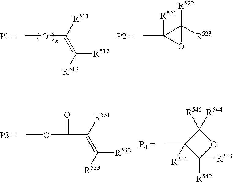
The invention relates to a liquid crystal composition comprising two or more species of liquid crystal compounds respectively having a polymerizable group, at least one species of which being a compound represented by formula (I) below, having a content of the compound of from 20% to 80% relative to the total mass of said two or more species of liquid crystal compounds. In formula (I), P1 represents a polymerizable group; each of L1 and L2 represents a divalent spacer group; each of Z1 to Z4 represents a divalent linking group; each of A1 and A2 represents a divalent cyclic group; each of m and n represents an integer from 0 to 3; MA represents any one group of A-I to A-V below:

Description

CROSS-REFERENCE TO RELATED APPLICATIONS[0001]This application claims benefit of priority under 35 U.S.C. 119 to Japanese Patent Application No. 2008-252930, filed on Sep. 30, 2008, which is expressly incorporated herein by reference in its entirety.BACKGROUND OF THE INVENTION[0002]1. Technical Field[0003]The present invention relates to a liquid crystal composition useful for preparing optical components such as optical compensation film, used for liquid crystal display devices and so forth, and a retardation film composed of the liquid crystal composition.[0004]2. Background Art[0005]Conventionally, polymerizable rod-like liquid crystal compounds have widely been used for producing optical compensation films. In the process of aligning the rod-like liquid crystalline molecules on an alignment film, the molecules at around the interface with the alignment film may horizontally be aligned with their longitudinal axes laid in parallel with the film surface, meanwhile the molecules at ...

Claims


Application Information

Patent Timeline
Patent Type & Authority Applications(United States)
IPC IPC(8): C09K19/34C09K19/32
CPCC09K2019/3408C09K19/322C09K19/3066Y10T428/10C09K2019/0466C09K19/32C09K2019/3416C09K19/2007C09K19/3411C09K2019/0407C09K2019/0448C09K2323/00
Inventor TAKEUCHI, HIROSHIICHIHASHI, MITSUYOSHIHAMASAKI, RYO
Owner FUJIFILM CORP
Learn More