Liquid crystal display

a liquid crystal display and liquid crystal technology, applied in the field of liquid crystal display, can solve the problems of insufficient reliability for commercial purposes, and insufficient heat and light resistance, and achieve the effects of reducing unsatisfactory display, stable liquid crystal alignment, and high contrast ratio

Active Publication Date: 2010-06-22
JAPAN DISPLAY INC +1
View PDF11 Cites 6 Cited by
  • Summary
  • Abstract
  • Description
  • Claims
  • Application Information

AI Technical Summary

Benefits of technology

[0042]It is an object of the present invention to provide a liquid crystal display, in particular a large size one, which can solve problems resulting from narrow production margin for alignment treatment as a major disadvantage characteristic of IPS-TFT-LCDs, reduce unsatisfactory display caused by distorted initial alignment direction, realize stable liquid crystal alignment, and produce high-quality images of increased contrast ratio.
[0095]As discussed above, the present invention can provide a liquid crystal display which can solve problems resulting from narrow production margin for alignment treatment as an inherent disadvantage involved in IPS-TFT-LCDs, reduce unsatisfactory display caused by distorted initial alignment direction, realize stable liquid crystal alignment, and produce high-quality images of higher contrast ratio.

Problems solved by technology

However, it involves the following problems viewed from commercial application.
The high-molecular-weight compounds, represented by polyvinyl cinnamate, having a high-molecular-weight-side chain into which a photo-reactive group is introduced, are not sufficiently reliable for commercial purposes, because of insufficient thermal stability of the aligned molecules.
Moreover, they are not always suitable for realizing strong alignment by aligning the liquid crystal molecules more uniformly, because the high-molecular-weight side chain is considered to work as the structural portion responsible for liquid crystal alignment.
Still more, a film of high-molecular-weight compound dispersed with a low-molecular-weight dichroic azo dye involves problems resulting from insufficient heat and light resistance, because the dye responsible for liquid crystal alignment is itself low in molecular weight.

Method used


Image

  • Liquid crystal display
  • Liquid crystal display
  • Liquid crystal display

Examples


example 1

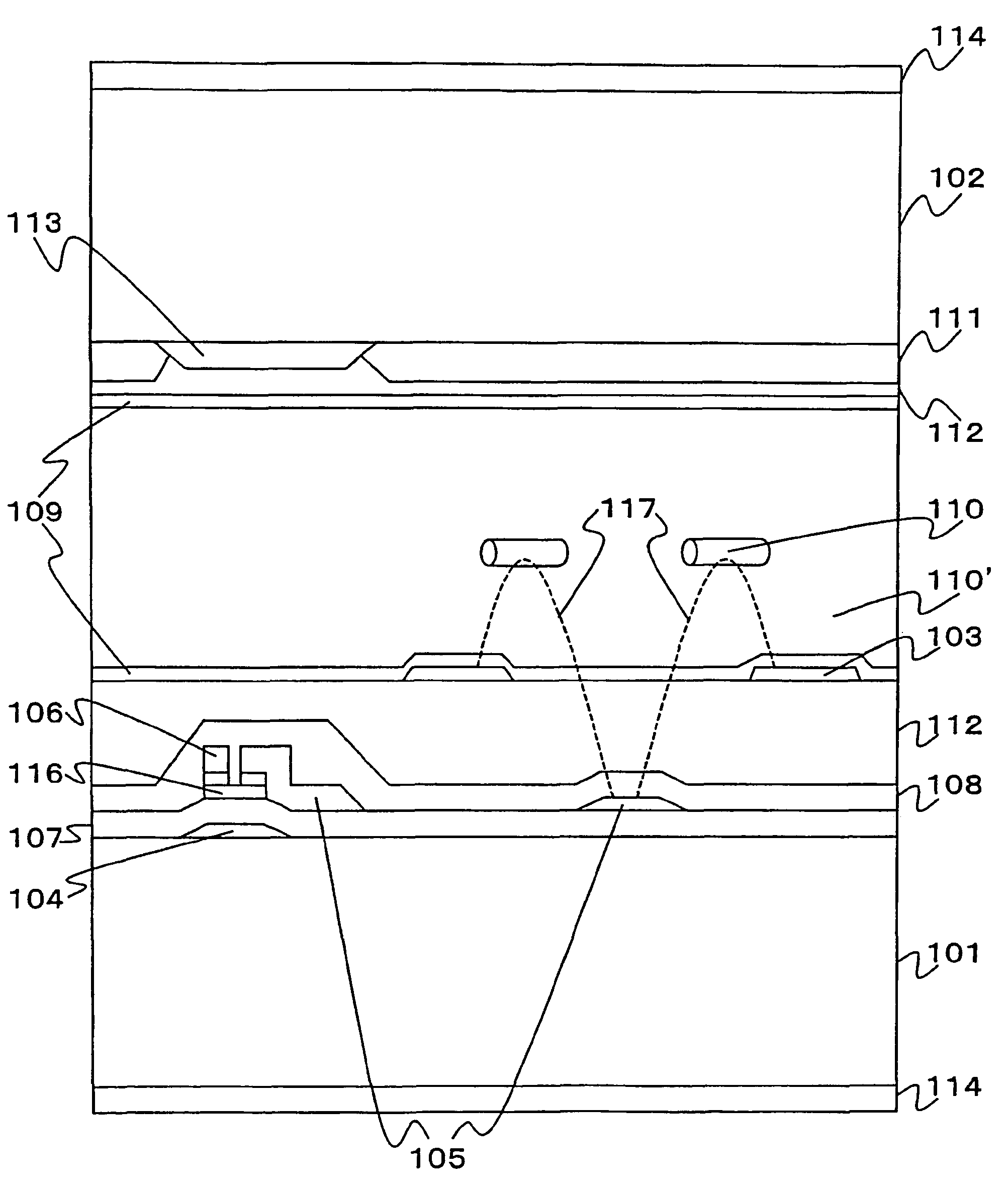
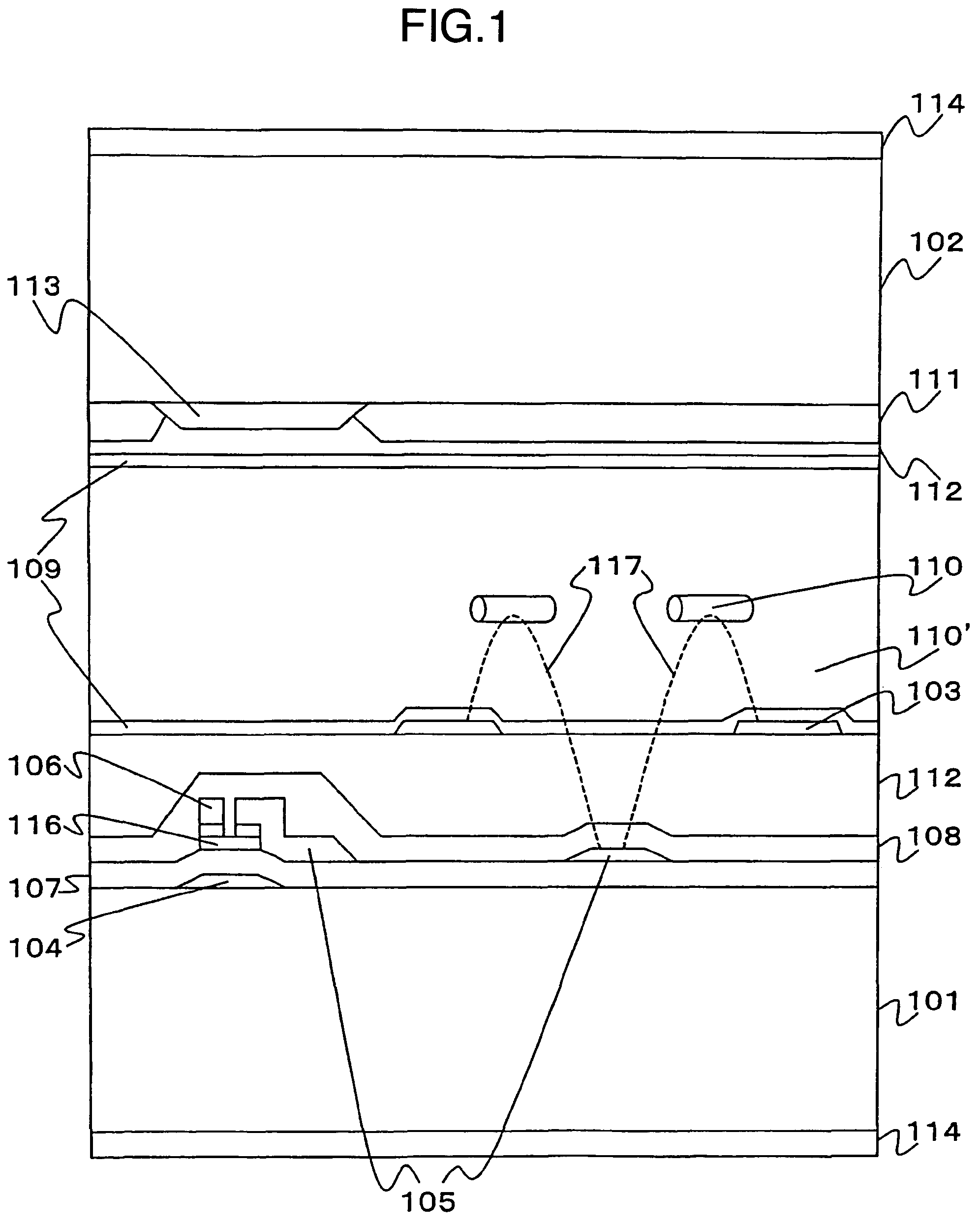
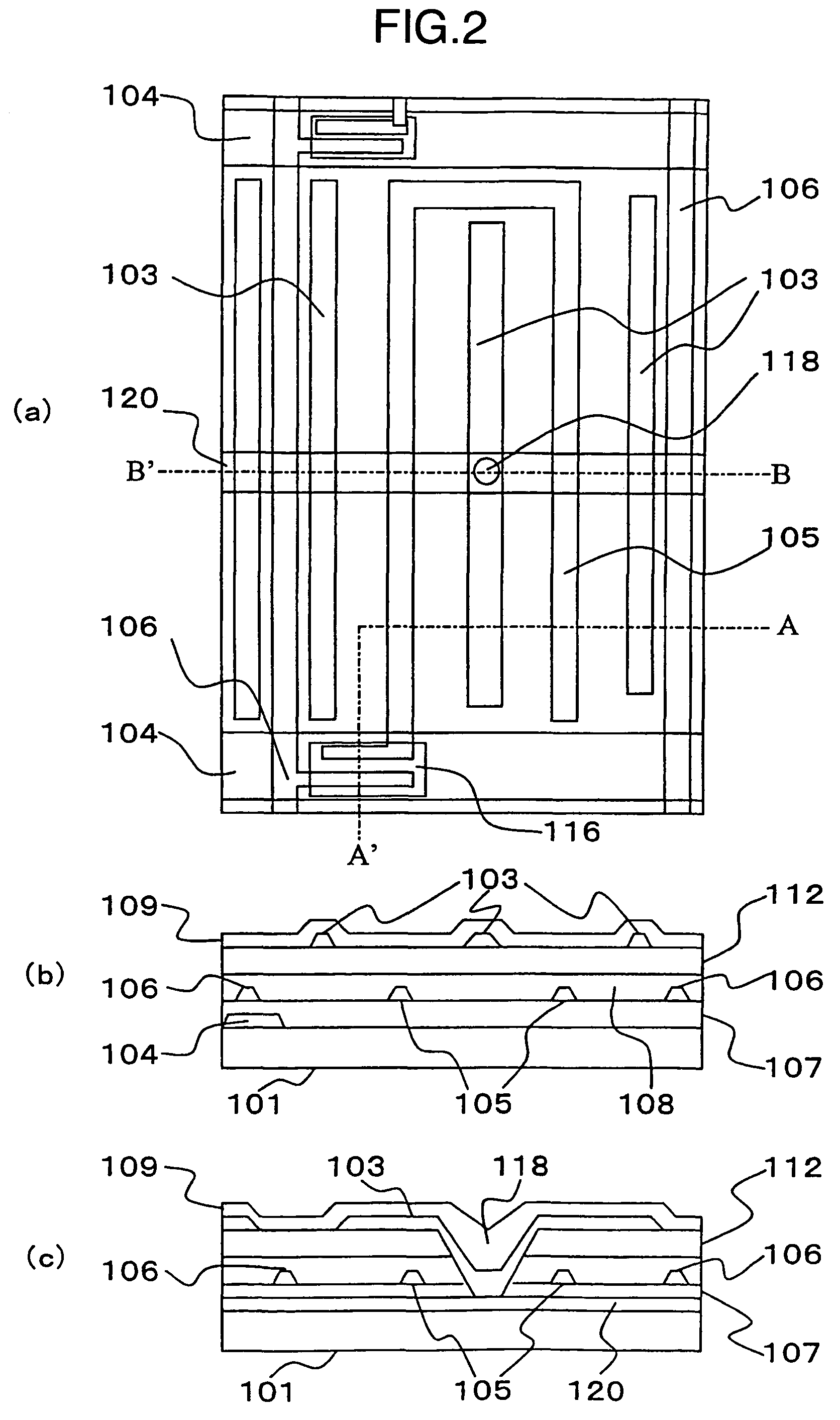
[0156]EXAMPLE 1 corresponds to the first embodiment of the present invention, described above. It is described in detail by referring to FIGS. 1 and 2.

[0157]For production of the liquid crystal display of the first embodiment of the present invention, a glass substrate surface-polished to a thickness of 0.7 mm is used for the substrate 101 as the active matrix substrate and substrate 102 as the opposite substrate (color filter substrate).

[0158]The thin-film transistor to be formed on the glass substrate 101 is composed of the source electrode (pixel electrode) 105, drain electrode (signal electrode) 106, gate electrode (scanning electrode) 104 and semiconductor film (of amorphous silicon) 116.

[0159]All of the scanning electrode 104, common electrode interconnection 120, signal electrode 106 and pixel electrode 105 are produced by patterning a chromium film, where the pixel electrode 105 and common electrode 103 are set 7 μm apart from each other.

[0160]A chromium film, which is low i...

example 2

[0182]A liquid crystal display is produced in the same manner as in EXAMPLE 1, except that a liquid crystal alignment layer is provided on the substrate by printing a polyamic acid varnish composed of tetracarboxylic dianhydride (represented by the general formula [Compound 25]) as an acid dianhydride and 3,4-diaminothiophene (represented by the general formula [Compound 26]) as a diamine compound, and heated at 220° C. for 30 minutes for imidization to have an about 40 nm thick film. It is then treated for photo-alignment with polarized ultraviolet ray of KrF excimer laser beams (wavelength: 248 nm) and nitrogen laser beams (wavelength: 337 nm).

[0183]

[0184]

[0185]The nematic liquid crystal composition A is sealed in the display as in EXAMPLE 1, and annealed at 100° C. for 10 minutes. The liquid crystal molecules are well-aligned, essentially at a right angle to the polarized light irradiation direction.

[0186]The liquid crystal display panel has the liquid crystal layer having a thic...

example 3

[0194]A liquid crystal display is produced in the same manner as in EXAMPLE 1, except that a liquid crystal alignment layer is provided on the substrate by printing a polyamic acid varnish composed of 1,3-dimethyl-1,2,3,4-cyclobutanetetracarboxylic dianhydride (represented by the general formula [Compound 29]) and pyromellitic acid dianhydride (represented by the general formula [Compound 30]) as acid dianhydrides (molar ratio: 7 / 3) and p-phenylenediamine (represented by the general formula [Compound 31]) as a diamine compound to a thickness of about 50 nm.

[0195]

[0196]

[0197]

[0198]The liquid crystal display is evaluated for quality of the images it produces in a manner similar to that for EXAMPLE 1. The images are confirmed to be of high quality, having a contrast ratio of above 550 / 1, almost on a level with that of the display produced in EXAMPLE 1, over the entire display area. A wide viewing angle is also confirmed during the gradation display period.

[0199]The display is quantitat...


PUM

PropertyMeasurementUnit
light wavelengthaaaaaaaaaa
thickaaaaaaaaaa
thickaaaaaaaaaa

Abstract

It is an object to provide a liquid crystal display which reduces unsatisfactory display caused by distorted initial alignment direction in a liquid crystal alignment layer for IPS type displays, realizes stable liquid crystal alignment, is high in mass-productivity, and produces high-quality images of increased contrast ratio. The liquid crystal display contains alignment layers 109 placed between a pair of substrates 101 and 102, at least one of which is transparent, liquid crystal layer 110′ sealed between the alignment layers, common electrode 103 and source electrode 105 for applying an electrical field to the liquid crystal layer, thin-film transistors connected to each of these electrodes, polarizer plate 114 provided on at least one of the substrates, wherein at least one of the alignment layers 109 is composed of a photo-reactive polyimide and / or polyamic acid which can be provided with a liquid crystal alignment capacity by being irradiated with essentially linearly polarized light.

Description

FIELD OF THE INVENTION[0001]The present invention relates to a liquid crystal display to which a photo-alignment method is applied.BACKGROUND OF THE INVENTION[0002]A liquid crystal display generally works by applying an electrical field to liquid crystal molecules in a liquid crystal layer placed between a pair of substrates to change a direction of the molecules to which they are aligned and thereby change optical characteristics of the liquid crystal layer.[0003]A liquid crystal display provided with a switching element, e.g., thin-film transistor, for each pixel, has an electrode at each of a pair of substrates which hold a liquid crystal layer in-between, and is designed to apply an electrical field to the layer in a direction essentially perpendicular to the substrate interface. This type of display, known as the so-called actively driven display, is represented by a twisted nematic (TN) display which works on optical rotation of the liquid crystal molecules constituting the li...

Claims


Application Information

Patent Timeline
Patent Type & Authority Patents(United States)
IPC IPC(8): G02F1/1337G02F1/1343G03C1/73G03C1/74C09K19/02C08G73/10C09K19/00
CPCG02F1/134363G02F1/133723G02F1/133788Y10T428/1023Y10T428/1018C09K2323/025C09K2323/027G02F1/1337
Inventor MATSUMORI, MASAKITOMIOKA, YASUSHIMATSUYAMA, SHIGERU
Owner JAPAN DISPLAY INC
Why Eureka
Try Eureka