Detachable vehicle-mounted banner assembly having improved display and mounting features

a vehicle-mounted banner and display technology, which is applied in the direction of flags/banners, display means, instruments, etc., can solve the problems of low durability of cloth flags, and achieve the effects of improving durability, maintaining readability, and improving durability

Active Publication Date: 2016-06-14
HARDFLAGS HLDG LLC
View PDF101 Cites 7 Cited by
  • Summary
  • Abstract
  • Description
  • Claims
  • Application Information

AI Technical Summary

Benefits of technology

[0005]As mentioned, many conventional automobile-mounted banners comprise a cloth flag mounted to a fixed mast which flaps in the wind. The performance of the cloth flag is highly dependent on the automobile's speed (e.g., too slow and the flag is not extended and not readable; too fast and the flag flaps too frequently to read). The durability of such cloth flags is also very low. Various embodiments of the invention described herein provide a configuration that not only improves durability but also maintains readability at any travelling speed. Certain embodiments replace conventional cloth flags with a substantially rigid body configured to maintain steady alignment with an imposed airflow. Certain embodiments having the substantially rigid body concurrently improve readability, as the “hard” flag is always extended regardless of travelling speed.
[0006]According to various embodiments, a detachable vehicle-mounted banner assembly having improved display and mounting features is provided. The banner assembly comprises: a banner panel defining two opposing and at least semi-rigid surfaces, the surfaces comprising at least a leading edge; a banner mast comprising a base portion and a flanged portion, the flanged portion comprising an angled leading edge and a trailing slot, the trailing slot being configured to selectively engage at least the leading edge of the banner panel; and a base assembly having a first portion configured for attachment adjacent a surface of a vehicle and a second portion configured to attachment relative to the base portion of the banner mast. The base portion of the banner mast is elongate and has a base longitudinal axis about which the banner mast and the banner panel pivot; and the flanged portion of the banner mast extends away from the base portion, is elongate, and has a flange longitudinal axis oriented at an acute angle relative to the base longitudinal axis.
[0007]According to various embodiments, a method of mounting a detachable vehicle-mounted banner assembly having improved display and mounting features is provided. The method comprises the steps of: fixedly attaching a base assembly to a surface of the vehicle, the base assembly having a first portion configured for attachment adjacent the surface of the vehicle and a second portion configured to attachment relative to a base portion of a banner mast of the banner assembly; and selectively attaching the banner mast to the second portion of the base assembly, the banner mast comprising a base portion and a flanged portion, the flanged portion comprising an angled leading edge and a trailing slot, the trailing slot being configured to selectively engage at least a leading edge of a banner panel.

Problems solved by technology

The durability of such cloth flags is also very low.

Method used


Image

  • Detachable vehicle-mounted banner assembly having improved display and mounting features
  • Detachable vehicle-mounted banner assembly having improved display and mounting features
  • Detachable vehicle-mounted banner assembly having improved display and mounting features

Examples


embodiment 10

[0099]General Construction of Embodiment 10

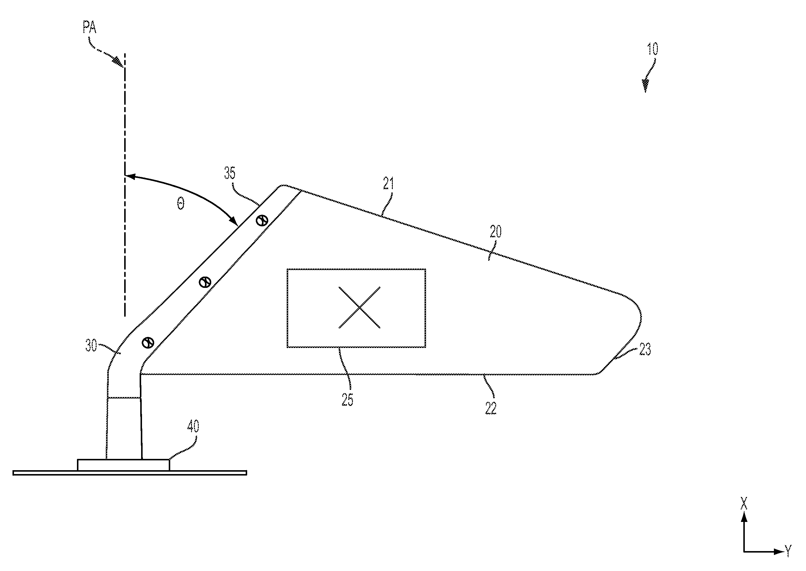
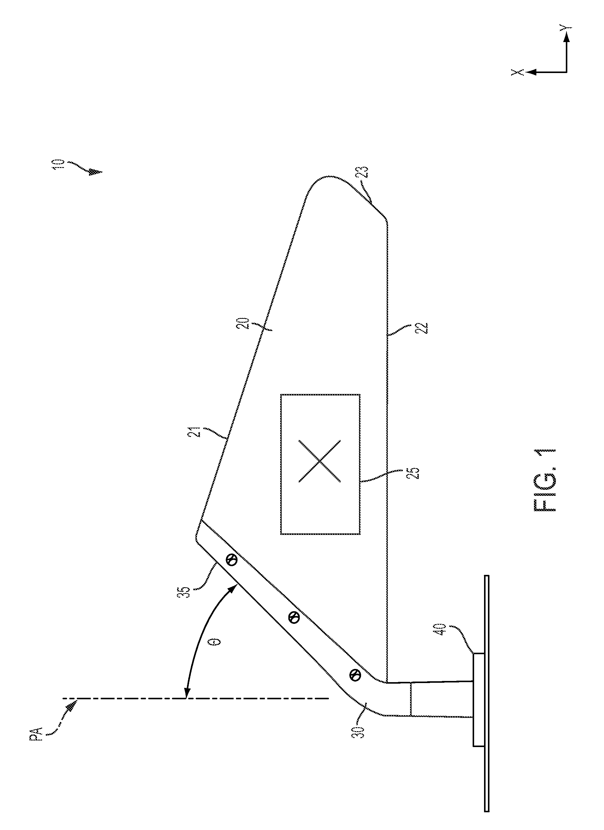
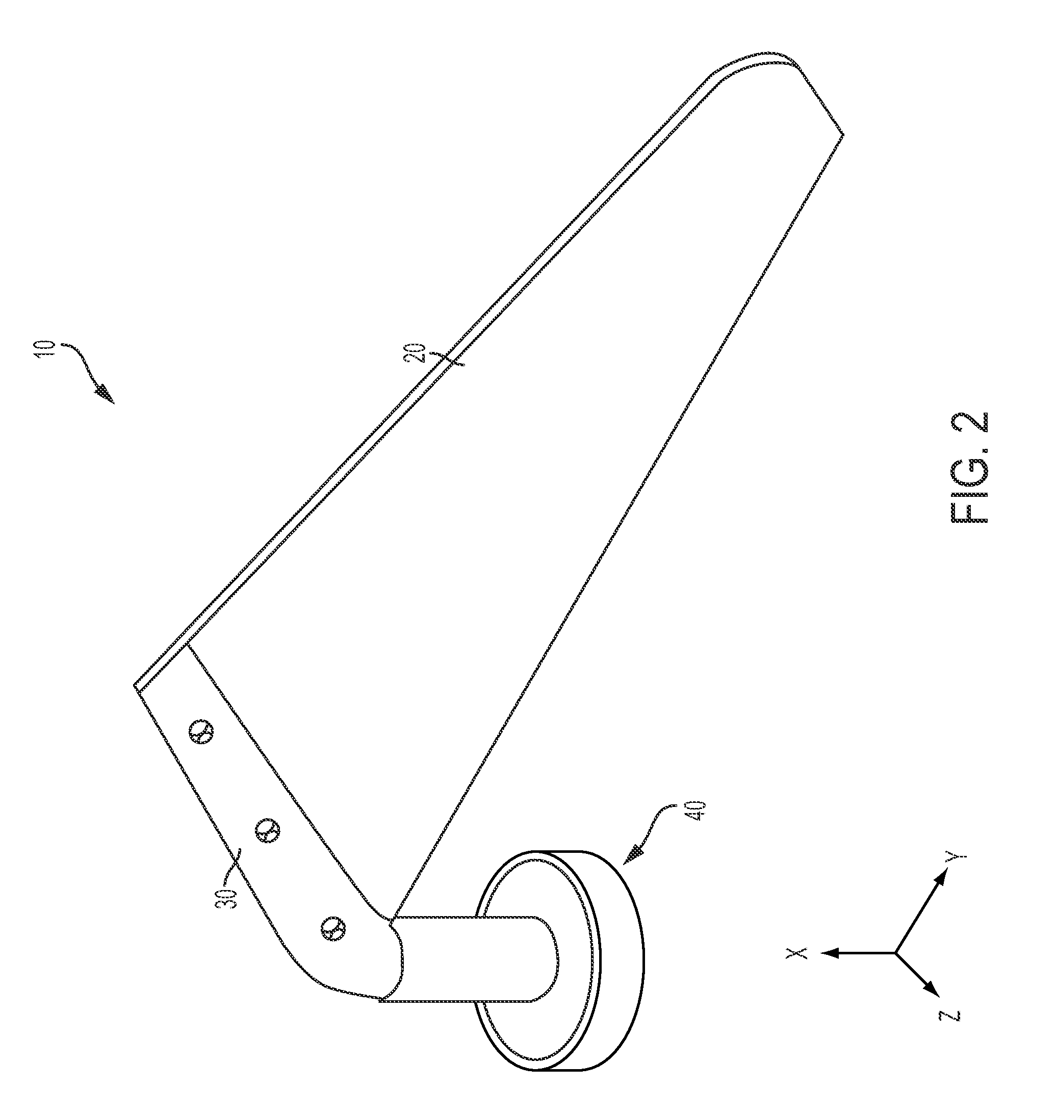
[0100]According to various embodiments, with reference to FIG. 1, the overall banner assembly 10 comprises:[0101]Banner Panel 20[0102]Banner Mast 30[0103]Magnetic Base Assembly 40 (including a post 41)[0104]Panel Mount Rivets 50[0105]Mast Retention Rivet 60

[0106]According to various embodiments, with continued reference to FIG. 1 and also reference to FIG. 4, the banner panel 20 is fixed to the banner mast 30, which defines an elongate mast cavity 32 (discussed below, typically downwardly oriented when in use). The elongate mast cavity 32 is configured in certain embodiments to accept an elongate post 41 (typically upwardly oriented when in use; see FIG. 4) which is part of the magnetic base assembly 40, and configured to pivot within the elongate mast cavity 32 about the substantially aligned longitudinal axes of the elongate mast cavity and the elongate post 41.

[0107]In certain embodiments, the banner mast 30 is fixed to the magnetic base...

embodiment 210

[0155]General Construction of Embodiment 210

[0156]According to various embodiments, with reference to FIGS. 11 and 12, the overall banner assembly 210 comprises:[0157]Banner Panel 220[0158]Banner Mast 230[0159]Magnetic Base Assembly 240 (including a post 241)[0160]Panel Mount Rivets 250 (see FIG. 12)[0161]Mast Retention Rivet 260 (see FIG. 12)

[0162]According to various embodiments, with continued reference to FIGS. 11-12, the banner panel 220 is fixed to the banner mast 230, which defines an elongate mast cavity 232 (not shown, but understandable via analogy to mast cavity 32 of assembly 10, as illustrated in FIG. 4 and described previously herein). With reference by analogy to cavity 32, according to various embodiments the elongate mast cavity 232 is configured in certain embodiments to accept an elongate post 241 (typically upwardly oriented when in use; see FIG. 12) which is part of the base assembly 240, and configured to pivot within the elongate mast cavity 232 about the subs...


PUM


Abstract

A detachable vehicle-mounted banner assembly is provided, comprising a banner panel defining two opposing and at least semi-rigid surfaces, the surfaces comprising at least a leading edge; a banner mast comprising a base portion and a flanged portion, the flanged portion comprising an angled leading edge and a trailing slot, the trailing slot being configured to selectively engage at least the leading edge; and a base assembly having a first portion configured for attachment to a vehicle and a second portion configured to attachment relative to the base portion. The base portion is elongate and has a base longitudinal axis about which the banner mast and the banner panel pivot; and the flanged portion of the banner mast extends away from the base portion and has a flange longitudinal axis oriented at an acute angle relative to the base longitudinal axis. A method of mounting the assembly is also provided.

Description

CROSS-REFERENCE TO RELATED APPLICATIONS[0001]This application claims priority to and the benefit of U.S. Provisional Patent Application Ser. No. 61 / 860,376, filed Jul. 31, 2013, the contents of which are hereby incorporated by reference in their entirety.BACKGROUND[0002]Many persons desire to display flags temporarily in a variety of locations fbr decorative purposes, as symbols of allegiance, support or affiliation, or as means for commercial advertising. As a non-limiting example, athletic team enthusiasts, such as college or high school students, their parents and relatives, as well as other team supporters, often wish to display a symbol, name, mascot, or color of their school as an expression of allegiance and support.[0003]A prime opportunity fir displaying a team's symbols occurs when supporters are traveling in a vehicle (e.g., a truck, car, or the like) to and from athletic events in which their favorite team is playing. Other situations also occur in which a person may wis...

Claims


Application Information

Patent Timeline
Patent Type & Authority Patents(United States)
IPC IPC(8): G09F17/00
CPCG09F17/00G09F2017/0075
Inventor BIGHAM, SHANNON HAROLDBIGHAM, JASON SLOANECOVERT, LANCE NICHOLASWARD, JR., JAMES HANSFORD
Owner HARDFLAGS HLDG LLC
Why Eureka
Try Eureka