Vanishing point detecting system, vanishing point detecting method, and vanishing point detecting program

a vanishing point detection and detection method technology, applied in the field of can solve the problems of weak noise in the detection system, inability of conventional vanishing point detection systems to perform robust vanishing point detection, etc., to suppress the detection of false vanishing points and the effect of robust detection of vanishing points

Active Publication Date: 2010-04-01
NEC CORP
View PDF13 Cites 24 Cited by
  • Summary
  • Abstract
  • Description
  • Claims
  • Application Information

AI Technical Summary

Benefits of technology

[0078]According to the present invention, with regard to each point in a two dimensional space including at least a portion of an image, by detecting, as the vanishing point, a point at which angles of a plurality of straight lines passing through the point or a vicinity thereof are sparsely distributed and dispersed over a wide range, robust detection of the vanishing point is realized. A reason for this is that the more the angles of the plurality of straight lines passing through a prescribed range surrounding the point in question are sparsely distributed and dispersed, the more likely it is that the point in question is detected as a vanishing point, thereby suppressing detection of a false vanishing point.

Problems solved by technology

The abovementioned conventional vanishing point detecting system has a problem in being weak with regard to noise.
That is, the conventional vanishing point detecting system cannot perform robust vanishing point detection.

Method used


Image

  • Vanishing point detecting system, vanishing point detecting method, and vanishing point detecting program
  • Vanishing point detecting system, vanishing point detecting method, and vanishing point detecting program
  • Vanishing point detecting system, vanishing point detecting method, and vanishing point detecting program

Examples


example 1

[0129]FIG. 4, FIGS. 5A and 5B are diagrams describing a specific example (one example) in which the present invention is carried out. FIG. 4 is an image taken of a road in a forward direction from an in-vehicle camera. That is, white lines 412 representing driving lanes and edge portions of the road edges 413 are detected as straight lines by the Hough transform, from a road image 410 obtained by taking an image of the road from a camera 520 installed in a vehicle 510, in FIG. 5A, and a vanishing point formed by these straight lines is detected. In FIG. 5A, a pitch angle θ is an angle between the vehicle 510 and the road surface 530 (the pitch angle θ is described later). FIG. 5B schematically illustrates relationships (an optical system) of a camera-optical axis 521 of the camera 520 installed in the vehicle 510 of FIG. 5A, a camera-image plane 522, a focal point and a focal length (FIG. 5B is described later).

[0130]FIG. 6A is a diagram showing one example of a configuration of the...

example 2

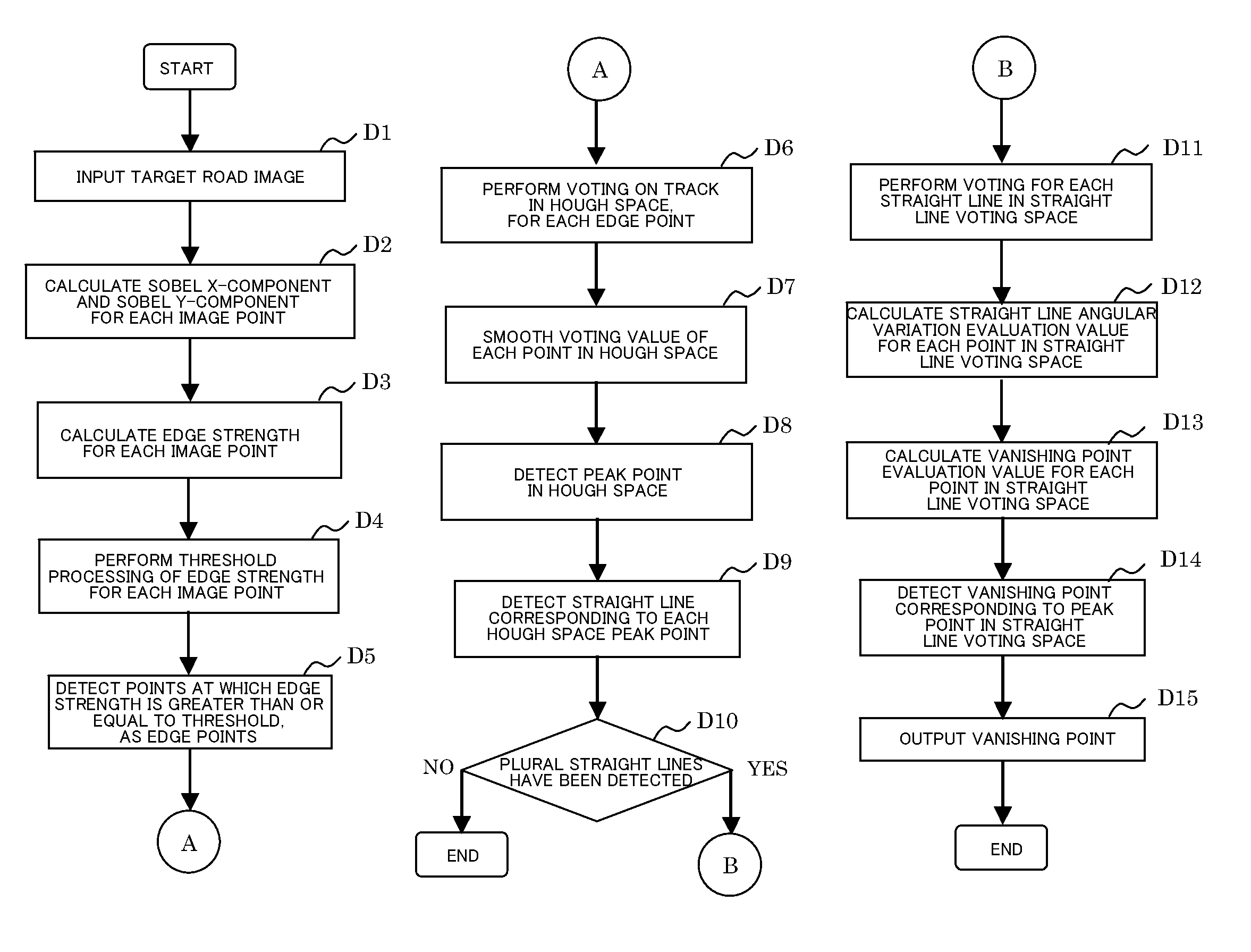
[0210]The present example detects, as straight lines, edge portions such as white lines 412 representing driving lanes, and road edges 413, by a Hough transform, from a road image 410 (an image taken of the road ahead from an in-vehicle camera), as shown in FIG. 4, and detects a vanishing point formed by these.

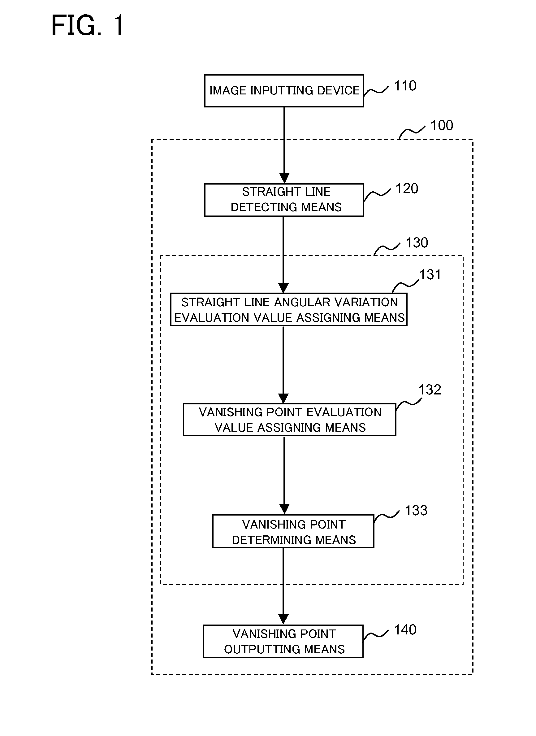
[0211]As shown in FIG. 13, the present example includes an image inputting device 1310 that includes an in-vehicle camera, a straight line detecting means (unit) 1320, a vanishing point detecting means (unit) 1330, and a vanishing point outputting means (unit) 1340.

[0212]The vanishing point detecting means 1330 includes a straight line voting means (unit) 1331, a straight line angular variation evaluation value assigning means (unit) 1332, a vanishing point evaluation value assigning means (unit) 1333, and a vanishing point determining means (unit) 1334.

[0213]FIG. 14A is a diagram showing a configuration of the straight line detecting means of FIG. 13. FIG. 14B is a diagram sh...


PUM


Abstract

Disclosed is a vanishing point detecting system that includes a straight line detecting unit, a vanishing point detecting unit, and a vanishing point outputting unit. In the vanishing point detecting unit, a vanishing point is detected with one evaluation index of vanishing point plausibility being whether or not angles of plural straight lines passing through a point in question or a vicinity thereof are sparsely distributed over a relatively wide range.

Description

CROSS-REFERENCE TO RELATED APPLICATIONS[0001]This application is the National Phase of PCT / JP2007 / 071546, filed Nov. 6, 2007 which claims the benefit of the priority of Japanese patent application No. 2006-302955 filed on Nov. 8, 2006, the disclosure of which is incorporated herein in its entirety by reference thereto.TECHNICAL FIELD[0002]The present invention relates to a vanishing point detecting system, a vanishing point detecting method, and a vanishing point detecting program, and in particular, relates to a vanishing point detecting system, a vanishing point detecting method, and a vanishing point detecting program that enable a vanishing point to be robustly detected from an image containing noise.BACKGROUND ART[0003]FIG. 18 is a diagram showing a configuration of a conventional vanishing point detecting system as disclosed in Patent Document 1. Referring to FIG. 18, this conventional vanishing point detecting system includes a main control unit 1810, an image inputting unit ...

Claims


Application Information

Patent Timeline
Patent Type & Authority Applications(United States)
IPC IPC(8): G06K9/46G06V10/48
CPCG06K9/00798G06K9/4633G06T7/0085G08G1/16G06T2207/10016G06T2207/30256G06T7/60G08G1/167G06T7/13G06V20/588G06V10/48
Inventor SAKURAI, KAZUYUKI
Owner NEC CORP
Why Eureka
Try Eureka