
Method and Apparatus for High Speed Silicon Optical Modulation Using PN Diode

a technology of pn diodes and optical modulators, applied in the field of optics, can solve the problems of limited speed at which this modulation can be done in part, and the challenge of high-speed optical modulation in silicon

Inactive Publication Date: 2010-04-01
INTEL CORP
View PDF6 Cites 85 Cited by
  • Summary
  • Abstract
  • Description
  • Claims
  • Application Information

AI Technical Summary

Benefits of technology

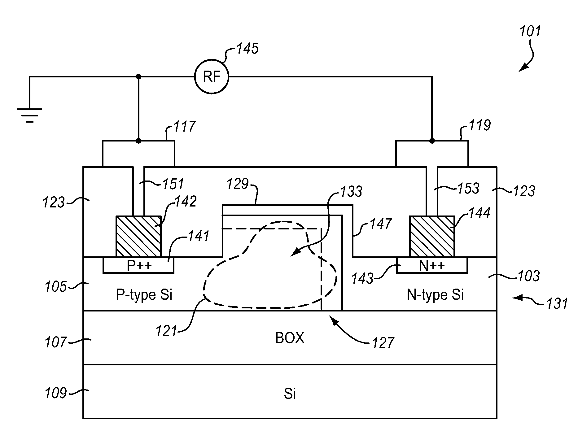
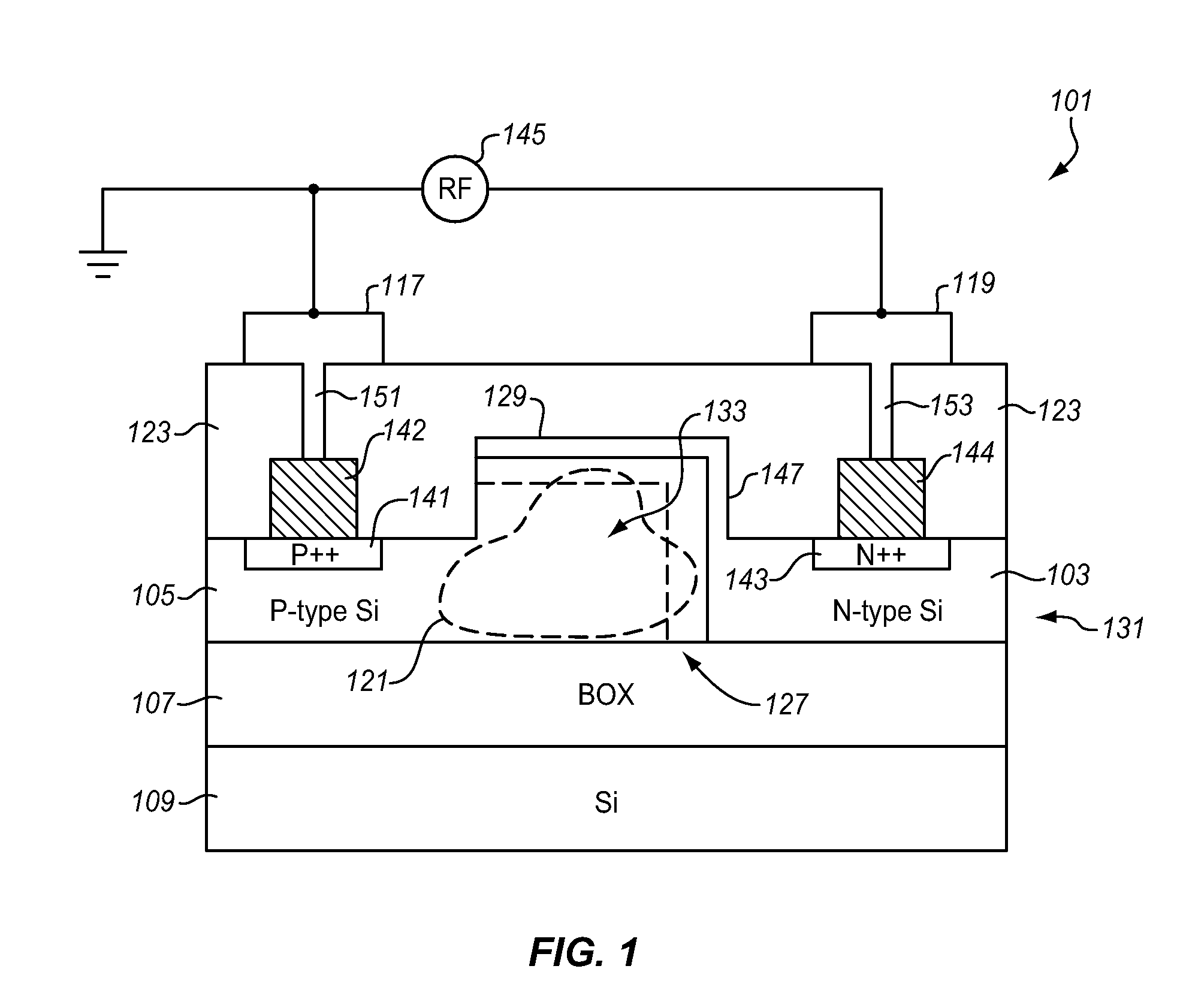
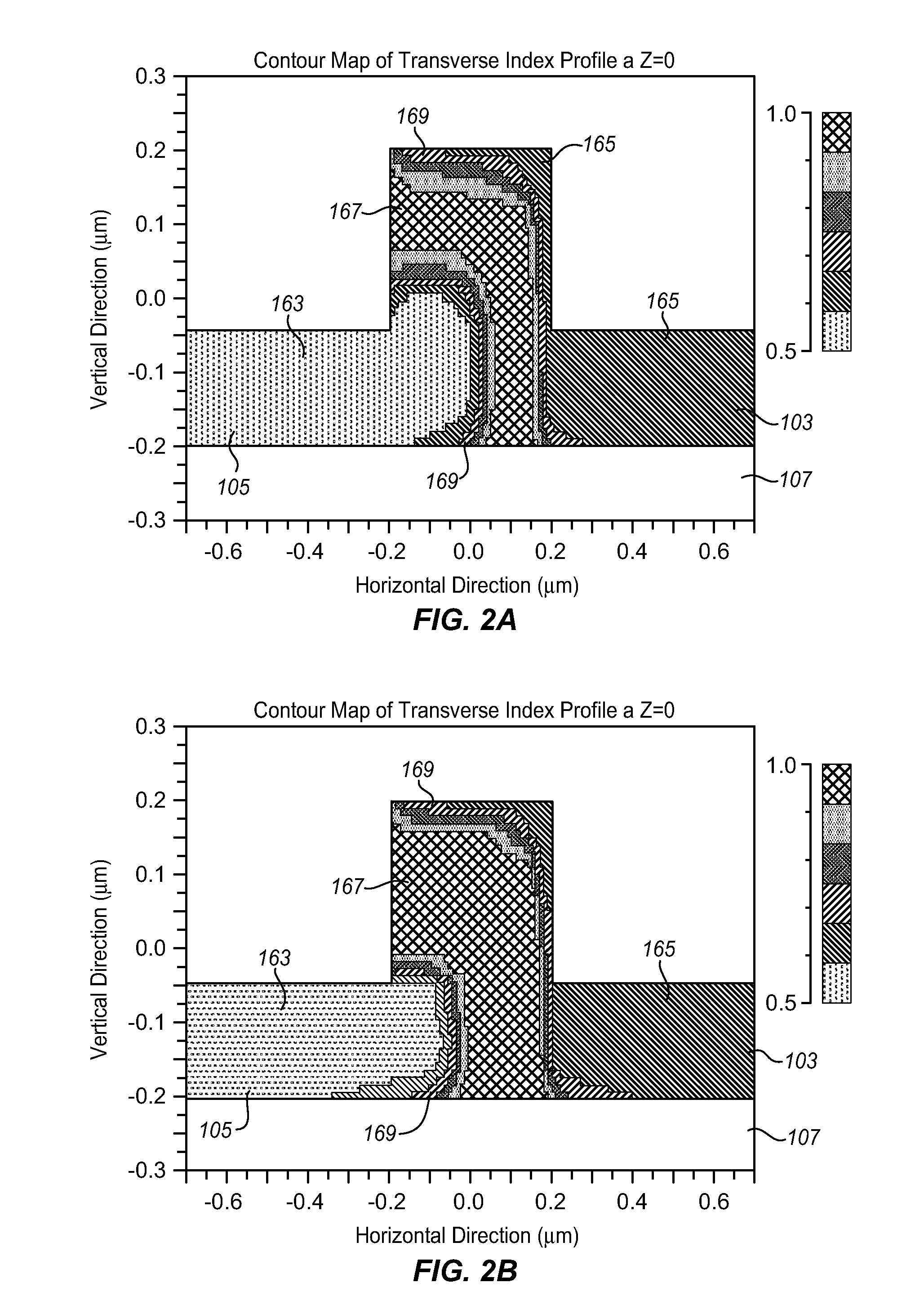
The present invention relates to optical modulators and, more specifically, to silicon optical modulators. The technical effect of the invention is to provide a high-speed optical modulator using reverse-biased pn diodes as an optical waveguide, with improved efficiency without requiring precise position control. The design of the pn diode can be changed to optimize depletion area and phase efficiency, and the configuration described below may be fabricated using a low energy angled implant without strict requirements on lithography registration control.

Problems solved by technology

An optical modulator is a key component of any optical communications link, however, it is challenging to achieve high speed optical modulation in silicon.
The speed at which this modulation can be done is limited in part by how fast the free carriers can be injected into or removed from the waveguide, the region occupied by the traveling optical mode.

Method used


Image

  • Method and Apparatus for High Speed Silicon Optical Modulation Using PN Diode
  • Method and Apparatus for High Speed Silicon Optical Modulation Using PN Diode
  • Method and Apparatus for High Speed Silicon Optical Modulation Using PN Diode

Examples


Embodiment Construction

[0012]In the following description numerous specific details are set forth in order to provide a thorough understanding of the present invention. It will be apparent, however, to one having ordinary skill in the art that the specific detail need not be employed to practice the present invention. In other instances, well-known materials or methods have not been described in detail in order to avoid obscuring the present invention.

[0013]Reference throughout this specification to “one embodiment” or “an embodiment” means that a particular feature, structure or characteristic described in connection with the embodiment is included in at least one embodiment of the present invention. Thus, appearances of the phrases “in one embodiment” or “in an embodiment” in various places throughout this specification are not necessarily all referring to the same embodiment. Furthermore, the particular features, structures or characteristics may be combined in any suitable manner in one or more embodi...


PUM


Abstract

A method and apparatus for high speed silicon optical modulation is described using a PN diode. In one example, an optical waveguide has adjoining first and second doped semiconductor regions. The first and second regions have opposite doping types and the first doped region extends in two perpendicular directions through the waveguide.

Description

BACKGROUND[0001]1. Field of the Invention[0002]The present invention relates generally to optics and, more specifically, the present invention relates to silicon optical modulators.[0003]2. Background Information[0004]Internet and network data traffic growth pushes toward optical-based data communication. Transmission of multiple optical channels over the same fiber in dense wavelength-division multiplexing (DWDM) systems and Gigabit Ethernet (GBE) systems provides a simple way to use the higher data capacity (signal bandwidth) offered by fiber optics. Commonly used optical components in data communications systems include wavelength division multiplexed (WDM) transmitters and receivers, optical filters such as diffraction gratings, thin-film filters, fiber Bragg gratings, arrayed-waveguide gratings, optical add / drop multiplexers, modulators, lasers and optical switches.[0005]Many of these building block optical components can be implemented in semiconductor devices. In electro-opti...

Claims


Application Information

Patent Timeline
Patent Type & Authority Applications(United States)
IPC IPC(8): G02B6/12
CPCG02B6/12004G02B2006/12142G02F1/2257G02F1/225G02F1/025G02B6/12G02B6/26
Inventor SHETRIT, YOELLIAO, LINGLIU, AMSHENG
Owner INTEL CORP
Learn More