
Method of Forming Registration Mark and Image Forming Apparatus

Inactive Publication Date: 2010-04-01
BROTHER KOGYO KK
View PDF4 Cites 27 Cited by
  • Summary
  • Abstract
  • Description
  • Claims
  • Application Information

AI Technical Summary

Benefits of technology

[0008]Accordingly, illustrative aspects of the present invention provide a method of forming a registration mark and an image forming apparatus which are capable of minimizing an effect of diffuse reflecting light such that scratches are less likely to be falsely detected as registration marks, and a registration mark which are capable of minimizing the occurrence of an offset.

Problems solved by technology

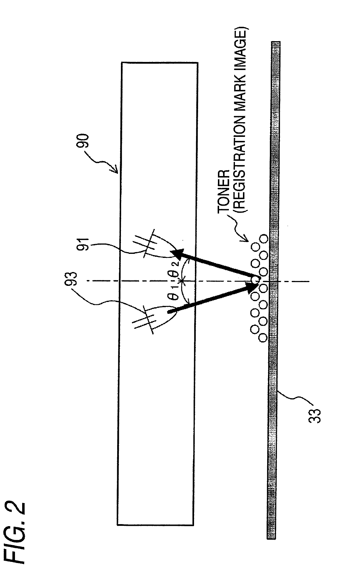
Further, in of the related art image forming apparatus, when there is a scratch, etc., on the conveyor belt, a light volume of specular reflecting light decreases at a position of the scratch, which may falsely detect the scratch as a registration mark.
The sensor that detects specular reflecting light is incapable of distinguishing the diffuse reflecting light from a specular reflecting light.
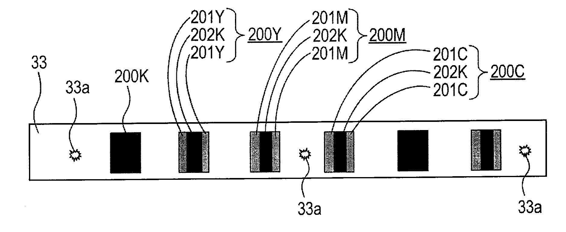
Thus, there is a disadvantage in that, because very little diffuse reflecting light is generated in a case of a black registration mark, a detected light volume greatly decreases at a central part of the registration mark.
However, in a case of a registration mark of a chromatic color, the diffuse reflecting light becomes intense near the center thereof, which suppresses a decrease in a detected light volume.
However, when the threshold value is made smaller, it becomes more difficult to prevent scratches, etc., from being falsely detected as registration marks.
Therefore, another disadvantage arises in that, when a diffuse reflecting light becomes strong, an offset may occur in which a position at which a detected light volume greatly decreases is shifted from a center of a registration mark.

Method used


Image

  • Method of Forming Registration Mark and Image Forming Apparatus
  • Method of Forming Registration Mark and Image Forming Apparatus
  • Method of Forming Registration Mark and Image Forming Apparatus

Examples


Embodiment Construction

[0021]Next, an exemplary embodiment of the present invention will be described with reference to the drawings. Note that, in the exemplary embodiments which will be hereinafter described, the present invention is applied to a so-called laser printer which is coupled to a computer.

1. External Configuration of Laser Printer

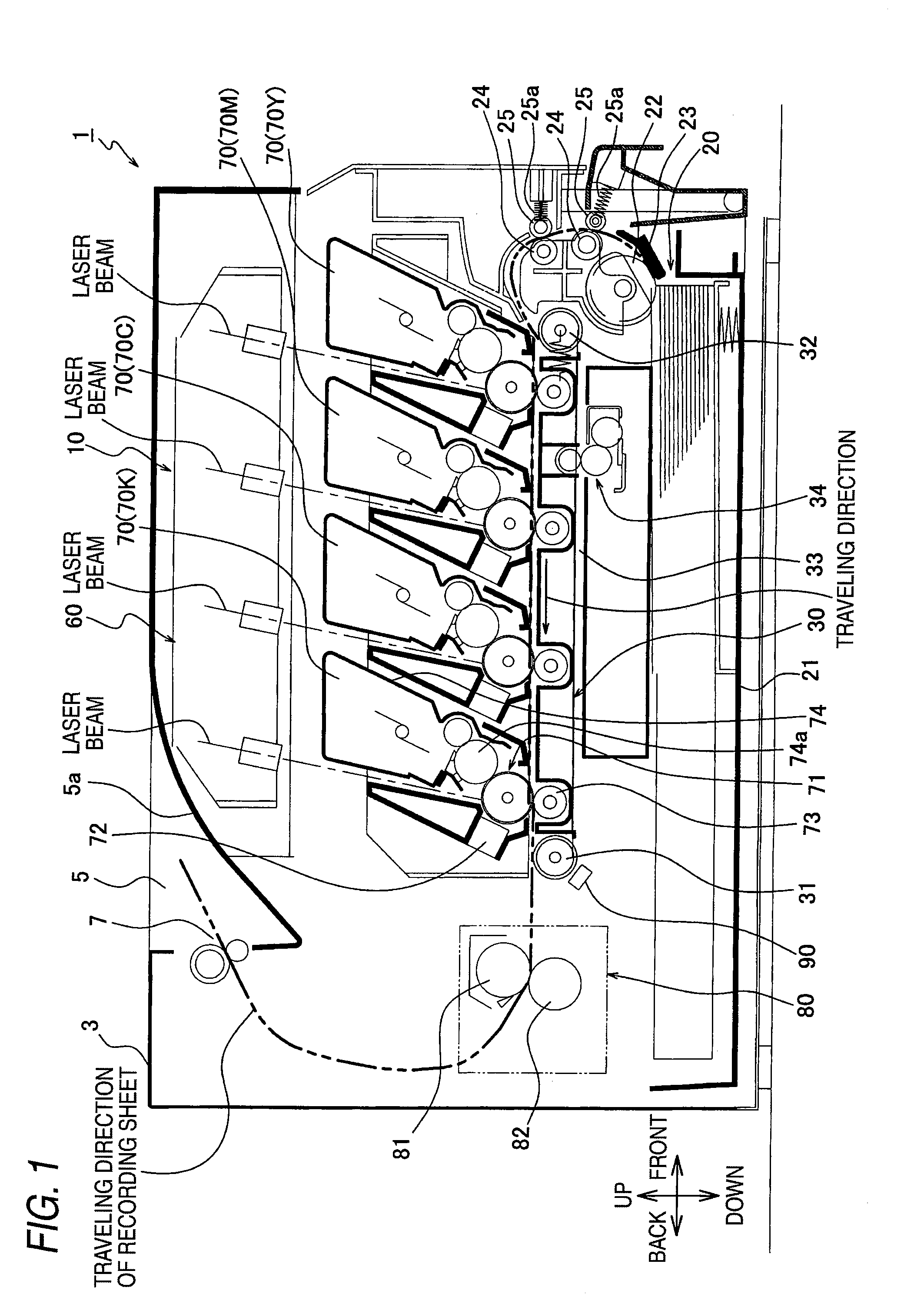
[0022]FIG. 1 is a side sectional view schematically showing an example of a configuration of a laser printer 1. The laser printer 1 is installed so that the upper side in FIG. 1 is upward in the direction of gravitational force, and is usually used so as to set the right side in FIG. 1 as the front side. Then, a case 3 of the laser printer 1 is formed into a substantially box shape (cubic shape), and a catch tray 5 on which recording sheets (corresponding to media to be recorded) such as papers or overhead projector (OHP) sheets to be discharged from the case 3 after completion of printing is provided at the upper surface side of the case 3.

[0023]Note that, in this ...


PUM


Abstract

A method of forming registration marks and an image forming apparatus are provided. The registration mark includes two first patterns and one second pattern on an image carrier. The method includes: forming two first patterns on the image carrier; and forming a second pattern on the image carrier between the two first patterns. A specular reflection component in a light reflected by the second pattern is less than a specular reflection component in a light reflected by the image carrier. A diffuse reflection component in a light reflected by the second pattern is less than a diffuse reflection component in a light reflected by the first pattern.

Description

CROSS-REFERENCE TO RELATED APPLICATIONS[0001]This application claims priority from Japanese Patent Application No. 2008-089726 filed on Mar. 31, 2008, the entire contents of which are incorporated herein by reference.TECHNICAL FIELD[0002]Methods and apparatuses consistent with the present invention relate to registration mark and, more particularly, to the formation and reading of registration mark.DESCRIPTION OF RELATED ART[0003]In a related art color image forming apparatus, registration marks of respective colors are formed on a surface of an image carrier such as a conveyor belt rotating in association with an operation of a process cartridge, and a shift in the images of the respective colors, etc., is corrected by detecting positions at which the registration marks are formed. The registration marks are scanned on the basis of a specular reflecting light of a light radiated onto the conveyor belt. That is, a sensor that detects a specular reflecting light is provided in the im...

Claims


Application Information

Patent Timeline
IPC IPC(8): G03G15/00G03G15/01
CPCG03G15/50G03G15/0194G03G2215/0161
Inventor TAKAHASHI, OSAMU
Owner BROTHER KOGYO KK
Learn More