Electrophotographic image forming apparatus

a technology of forming apparatus and forming cartridge, which is applied in the direction of electrographic process apparatus, optics, instruments, etc., can solve the problems of inadvertent contact between the developing roller and the photosensitive drum of the electrophotographic image, and the user may unintentionally contact the developing roller and the electrophotographic image, so as to improve the operation at the time of the exchange of the developing cartridg

Active Publication Date: 2010-04-01
CANON KK
View PDF9 Cites 108 Cited by
  • Summary
  • Abstract
  • Description
  • Claims
  • Application Information

AI Technical Summary

Benefits of technology

[0006]According to the present invention, the operativity at the time of the exchange of the developing cartridge is improved. In addition, according

Problems solved by technology

For this reason, at the time of an exchanging operation of the developing cartridge, there is a possibility that a user may unintentionally contact to the developing

Method used


Image

  • Electrophotographic image forming apparatus
  • Electrophotographic image forming apparatus
  • Electrophotographic image forming apparatus

Examples


embodiment 1

[0029]Referring to FIG. 1-FIG. 11, an electrophotographic image forming apparatus (image forming apparatus) according to Embodiment 1 of the present invention will be described.

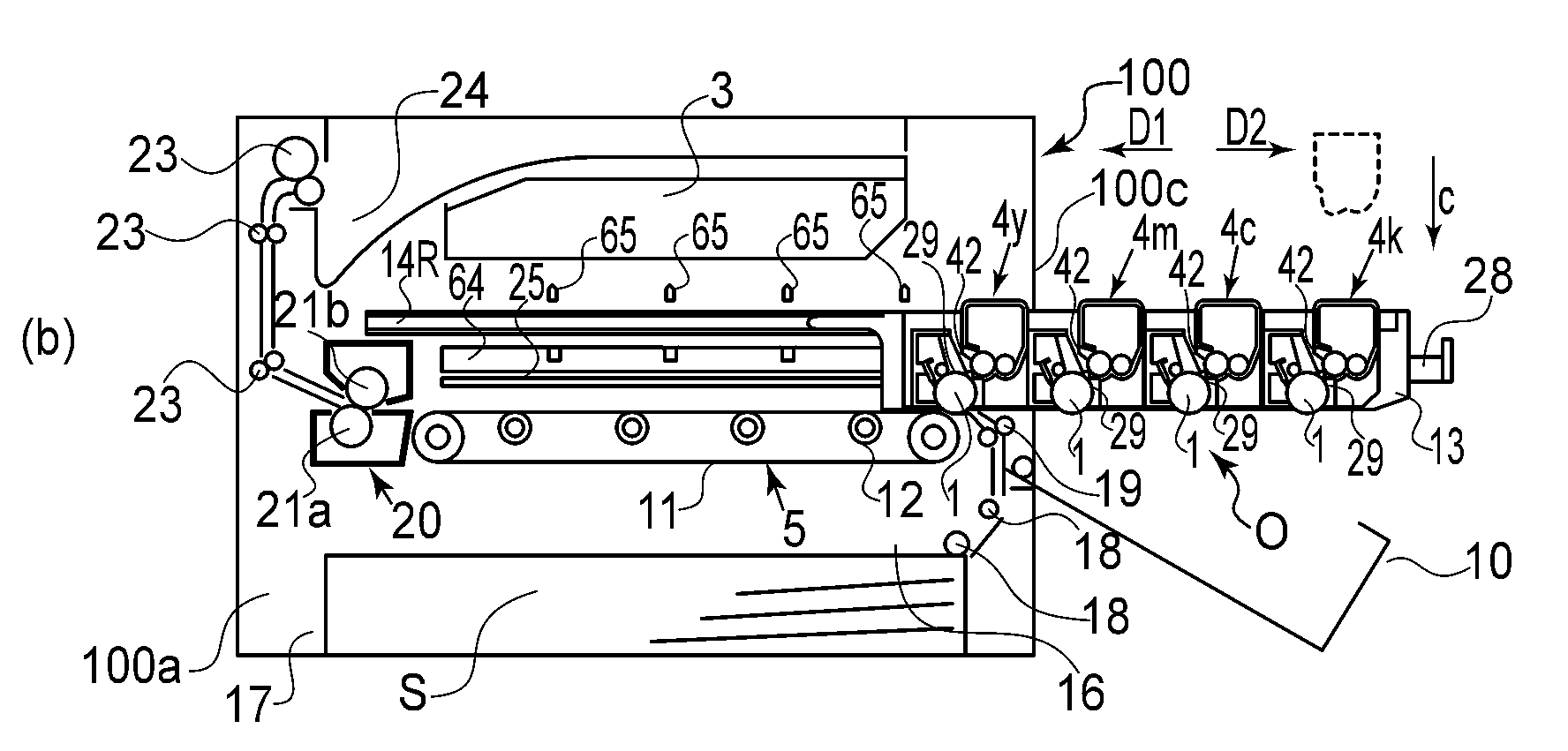
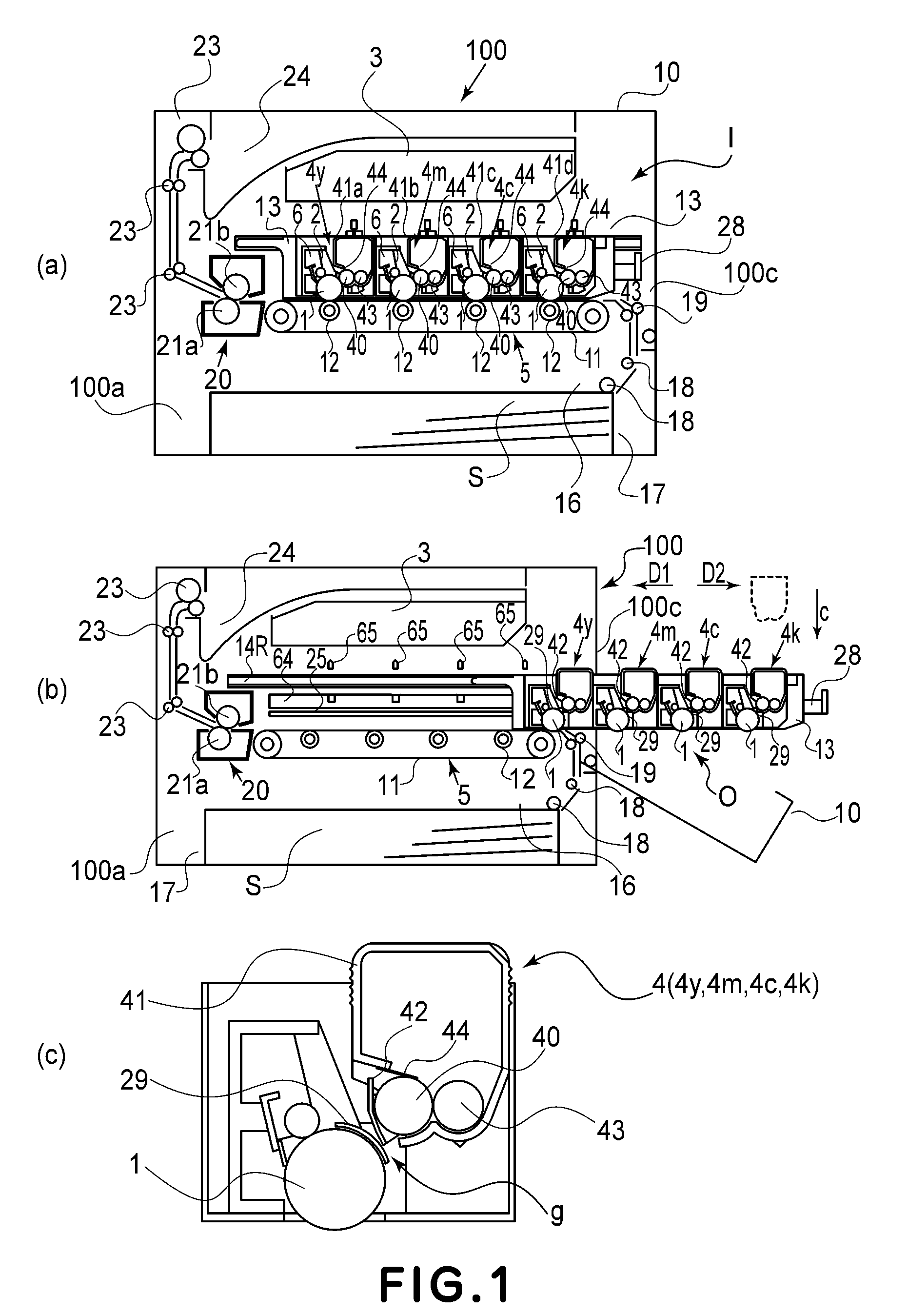
[0030]Referring to FIG. 1, the description will be made as to the structure of the image forming apparatus according to Embodiment 1 of the present invention. FIG. 1 is a sectional view (a) of the image forming apparatus. In FIG. 1, (b) is a sectional view illustrating the state that the drawer member is pulled out. In FIG. 1, (c) is an enlarged view of a part of a structure shown in (a) and (b) (adjacent the developing cartridge)).

[0031]The image forming apparatus 100 according to the present embodiment is provided with the four electrophotographic photosensitive drums 1 (photosensitive drum or arranged in a horizontal direction relative to an installation surface (unshown)). A drum 1 is rotated clockwisely by driving means (unshown)(FIG. 1 (a)). In addition, the image forming apparatus 100 is provided with ...

embodiment 2

[0077]Referring to (b) of FIG. 13-FIG. 16, Embodiment 2 of the present invention will be described. In Embodiment 1, the shutter 42 operates interrelatedly with the movement of the drawer member 13. In this embodiment, an opening and closing of the shutter for protecting the developing roller is done interrelatedly with the mounting and demounting operation of the cartridge relative to the drawer member. The like reference numerals as in the foregoing embodiments are assigned to the elements having the corresponding functions

[0078]FIG. 13 is a perspective view of the developing cartridge according to Embodiment 2. And, (a) of FIG. 14 is a perspective view of the drawer member according to Embodiment 2. Here, (b) of FIG. 14 is a perspective view illustrating the state of mounting the developing cartridge to the drawer member. In (b) of FIG. 14, the structures of the main assembly are schematically shown for better illustration. FIG. 15 shows the mechanism at the time of mounting the ...

embodiment 3

[0087]Referring to FIG. 17 and FIG. 18, Embodiment 3 of the present invention will be described. The photosensitive drum, the charging member, the cleaning member, and so on are fixed to the drawer member in Embodiment 1. In this embodiment, these are provided in the main assembly (100a) and only the developing cartridge is mounted to the drawer member. The like reference numerals as in the foregoing embodiments are assigned to the elements having the corresponding functions.

[0088]Here, (a) of FIG. 17 shows an image forming apparatus according to Embodiment 3, and is a sectional view illustrating the state that the drawer member is pulled out. And, (b) of FIG. 17 is a sectional view illustrating the state that the drawer member is mounted in the main assembly and the door is opened in the image forming apparatus according to Embodiment 3. FIG. 18 is a sectional view of the image forming apparatus according to Embodiment 3.

[0089]The present embodiment is different the above described...


PUM


Abstract

An electrophotographic image forming apparatus includes an electrophotographic photosensitive drum; a developing cartridge including a developing roller for developing a latent image formed on the drum, a developer accommodating portion for accommodating a developer to be used by the developing roller to develop the electrostatic latent image, and a developing roller shutter movable between a protecting position for covering a part of a peripheral surface of the developing roller and a retracted position, retracted from the protecting position, for exposure the part of the peripheral surface of the developing roller, wherein the developing cartridge is detachably mountable to a main assembly of the apparatus; a cartridge supporting member movable, while detachably mounting the developing cartridge, between an inside position which is inside of the main assembly of the apparatus to Mount the developing cartridge to the main assembly of the apparatus and an outside position which is outside of the main assembly of the apparatus to remove the developing cartridge from the main assembly of the apparatus; a force receiving portion, provided on the developing cartridge, for receiving a force for moving the developing roller shutter from the protecting position to the retracted position; and a force applying portion provided in the main assembly of the apparatus, wherein when the cartridge supporting member is moved from the outside position to the inside position, the force receiving portion contacts to the force applying portion to move the cartridge supporting member from the outside position to the inside position, in interrelation with which the force receiving portion contacted to the force applying portion receives the force from the force applying portion, thus moving the developing roller shutter from the protecting position to the retracted position.

Description

FIELD OF THE INVENTION AND RELATED ART[0001]The present invention relates to an electrophotographic image forming apparatus.[0002]The electrophotographic image forming apparatus forms an image on a recording material using an electrophotographic image forming process. And, the examples of the electrophotographic image forming apparatus include an electrophotographic copying machine, an electrophotographic printer (a laser beam printer, and LED printer, for example) and a facsimile device. The recording material is the material on which the image is formed by the electrophotographic image forming apparatus, and they are paper or an OHP sheet, for example. Using a drawer member which can be drawn in and out relative to a main assembly is known in the field of the electrophotographic image forming apparatus. With such a structure, while supporting a plurality of cartridge the drawer member is pushed into the main assembly. By this, the cartridge can be mounted to the inside of the main...

Claims


Application Information

Patent Timeline
IPC IPC(8): G03G21/18G03G15/04
CPCG03G21/1853G03G21/16G03G2221/1684G03G21/1671G03G21/1676G03G15/0865G03G21/1647
Inventor KIKUCHI, KEN
Owner CANON KK
Why Eureka
Try Eureka