
Remote controlled vehicle for threading a string through HVAC ducts

a remote control vehicle and duct technology, applied in the direction of remote control toys, cables, cables, etc., can solve the problems of airflow coming from all of the leakage in the duct system, the method is not working well for some duct systems and specific duct paths, and the control wires cannot be easily accessible from the damper

Inactive Publication Date: 2010-04-01
EMME E2MS
View PDF0 Cites 33 Cited by
  • Summary
  • Abstract
  • Description
  • Claims
  • Application Information

AI Technical Summary

Benefits of technology

[0020]Another object is to provide a remote controlled vehicle to assist in threading string in a HVAC duct system that is smaller, less expensive, and more functional than the prier art.

Problems solved by technology

Although the duct is accessible for damper installation, there may be no easily accessible path to run control wires from the damper to the control system because portions of the duct may be enclosed in walls, floors, or ceilings.
However, this method does not work well for some duct systems and specific duct paths.
However, the airflow can also come for all of the leaks in the duct system.
If the leakage is excessive, there is insufficient airflow at the vent to inflate and pull the parachute.
In a small vent, a large portion of the parachute is in contact with the walls of the duct creating a large drag, and screws or sharp edges are likely to snag the parachute.
Increasing the air flow to increase the pulling force also increases the drag since parts of the parachute are pushed harder against the duct walls.
The combination of high drag and small force makes it difficult for the parachute to pass through the duct.
As the duct cross-section increases, the air velocity decrease and the small parachute can not product enough force to pull the string to the HVAC equipment.
In some duct networks with long duct runs with many turns, the resistance between the string and the duct walls become excessive as the length of the string being pulled increases.
The force generated by the parachute is not sufficient to overcome the string pulling friction.
However, they are not adapted for use in HVAC trunks and for the purpose of capturing a string or parachute.
It did not provide video camera and display for showing the inside of the ducts as it traveled.
The vehicle followed the walls of the duct and provided no method for remote controlled steering.
It did not provide video camera and display for showing the inside of the ducts as it traveled.
They were too large to fit in many trunks routinely used in residential HVAC systems.
They did not have a moveable tool adapted to capture string or a moveable video camera adapted to searching for string.

Method used


Image

  • Remote controlled vehicle for threading a string through HVAC ducts
  • Remote controlled vehicle for threading a string through HVAC ducts
  • Remote controlled vehicle for threading a string through HVAC ducts

Examples


Embodiment Construction

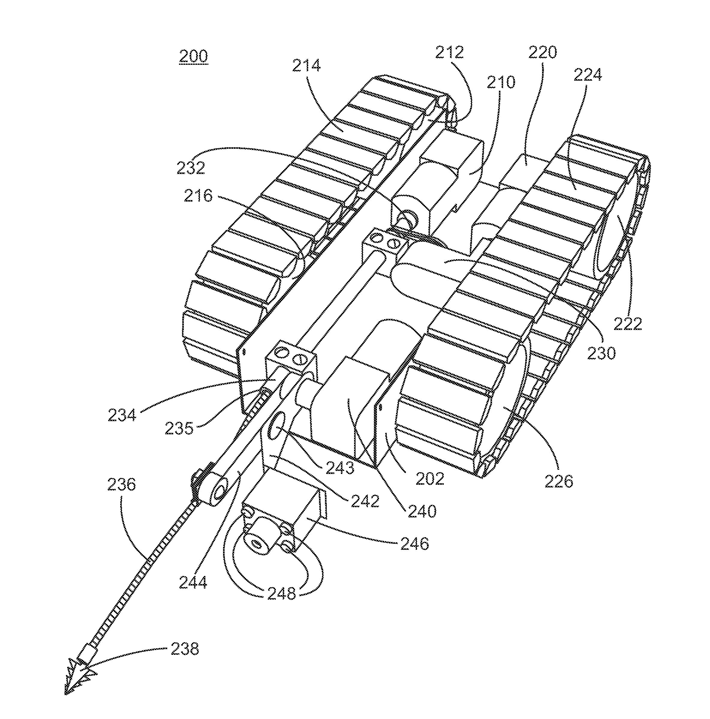
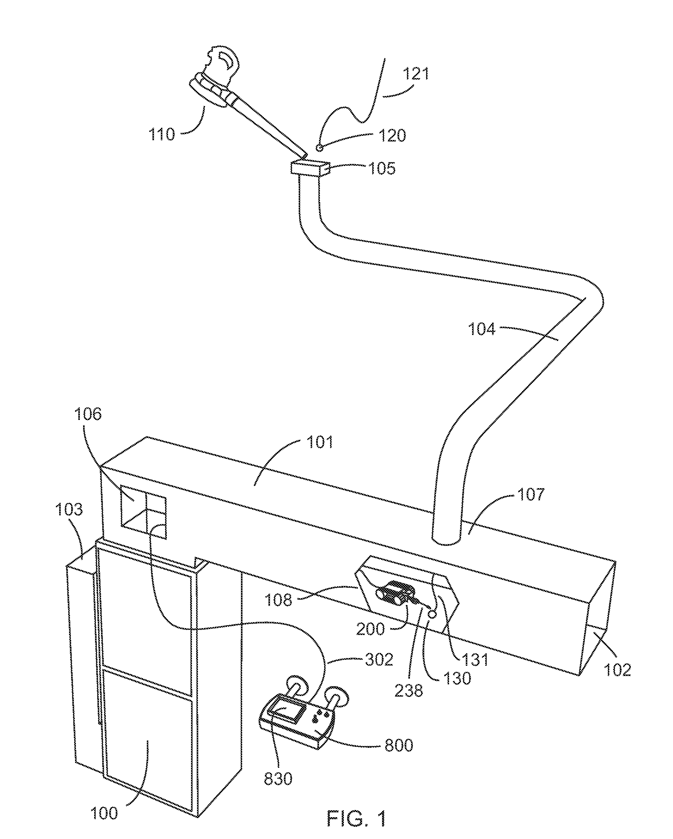
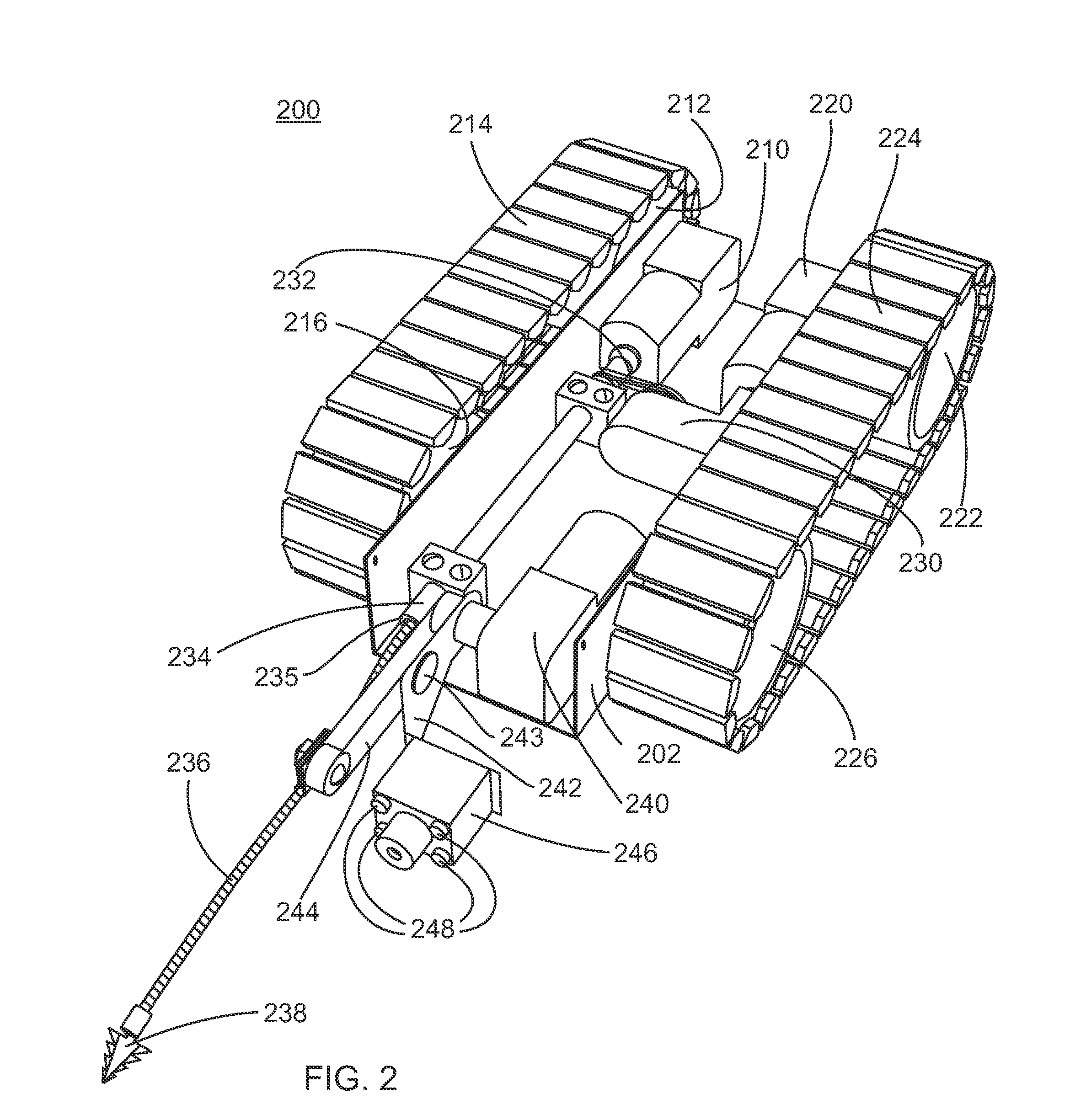
[0040]FIG. 1 is a perspective view of a typical HVAC system found in residential dwellings. HVAC equipment 100 includes a fan for generating a flow of warmed or cooled air through a network of supply ducts that distribute the air through out the dwelling. The duct network includes a main trunk 101 connected to the supply plenum of the HVAC equipment 100. Only a small section of the main trunk is shown. The open end 102 is connected to the remainder of the duct network. A smaller duct 104 connects to the main trunk at 107 and provides a path for airflow to vent 105. There are one or more vents in each room of the dwelling. Each of the other vents is connected to a smaller duct that also connects to the main trunk. Dwellings typically have 10 to 30 vents; only one vent of many is shown in FIG. 1. Air is returned to the HVAC equipment through duct 103 which is connected to one or more large centrally located return vents in the dwelling. In many dwellings, the duct network is enclosed ...


PUM


Abstract

The invention is a remote controlled vehicle adapted for navigating inside HVAC supply trunks. It is equipped with a moveable camera and a powered tool for snagging a string or parachute propelled into the trunk by other methods. A command box is provided to view the image from the camera and control the vehicle's various functions. The installation technician inserts the vehicle into the trunk through an access hole and uses the command box to navigate the vehicle inside a HVAC trunk and locate and secure the string to the vehicle. The technician then controls the vehicle to pull the string back to the access or the technician manually pulls the vehicle back to the access by its tether.

Description

BACKGROUND OF THE INVENTION[0001]1. Technical Field of the Invention[0002]This invention relates generally to HVAC zone control systems for retrofit, and specifically to a remote controlled vehicle to assist in threading string, air tubes, and wires through concealed HVAC duct systems.[0003]2. Background Art[0004]Most zone control systems for HVAC systems use electromechanical dampers to selectively control the airflow through portion of the trunk and duct system. Installation of these zone systems requires access to the ducts at multiple locations so that the dampers can be installed. Although the duct is accessible for damper installation, there may be no easily accessible path to run control wires from the damper to the control system because portions of the duct may be enclosed in walls, floors, or ceilings. However the duct system does provide a clear path provided the zone control equipment is located near the HVAC equipment. The existing ductwork can be used as a conduit for ...

Claims


Application Information

Patent Timeline
Patent Type & Authority Applications(United States)
IPC IPC(8): A63H30/04
CPCA63H30/04
Inventor ALLES, HAROLD GENE
Owner EMME E2MS
Learn More