
Line Tapping Method of Video Amplification for Unshielded Twisted Pair Active Receiver

Active Publication Date: 2010-04-01
PELCO INC
View PDF17 Cites 4 Cited by
  • Summary
  • Abstract
  • Description
  • Claims
  • Application Information

AI Technical Summary

Benefits of technology

[0014]In one aspect, embodiments of the invention concern an apparatus for amplifying a video signal that can include: a plurality of amplifiers each configured to receive at least one configuration signal, wherein a first of the plurality of amplifiers is further configured to receive the video signal; an analog switch configured to (i) receive the video signal, a signal from each of the plurality of amplifiers, and the at least one configuration signal and (ii) generate an amplified video signal; and a control unit configured to (i) receive the amplified video signal and (ii) generate the at least one configuration signal, wherein the plurality of amplifiers are configured to be enabled in response to the at least one configuration signal and the analog switch is configured in response to the at least one configuration signal.
[0015]In another aspect, embodiments of the invention concern an apparatus for amplifying a video signal that can include: a pre-processing circuit configured to receive a signal from a differential transmission line and generate the video signal, the pre-processing circuit comprising a preamplifier and a DC restore circuit; a plurality of amplifiers configured in series, each configured to receive at least one configuration signal, wherein a first of the plurality of amplifiers is further configured to receive the video signal; an analog switch configured to (i) receive the video signal, a signal from each of the plurality of amplifiers, and the at least one configuration signal and (ii) generate an amplified video signal; at least one user mode control signal received from the group consisting of a switch, a button, a potentiometer, and a jumper; a control unit comprising a sync separator and configured to (i) receive the amplified video signal and the at least one user mode control signal and (ii) generate the at least one configuration signal in response to the amplitude of a color burst portion of the amplified video signal and the at least one user mode control signal, wherein the plurality of amplifiers are configured to be enabled in response to the at least one configuration signal and the analog switch is configured in response to the at least one configuration signal; and a post-processing circuit configured to receive the amplified video signal and generate a differential amplified video signal, the post-processing circuit comprising a differential amplifier.
[0016]In other embodiments, the invention

Problems solved by technology

Although coaxial cable can be used as a transmission line in smaller installations, it is cost prohibitive in the majority of large installations.
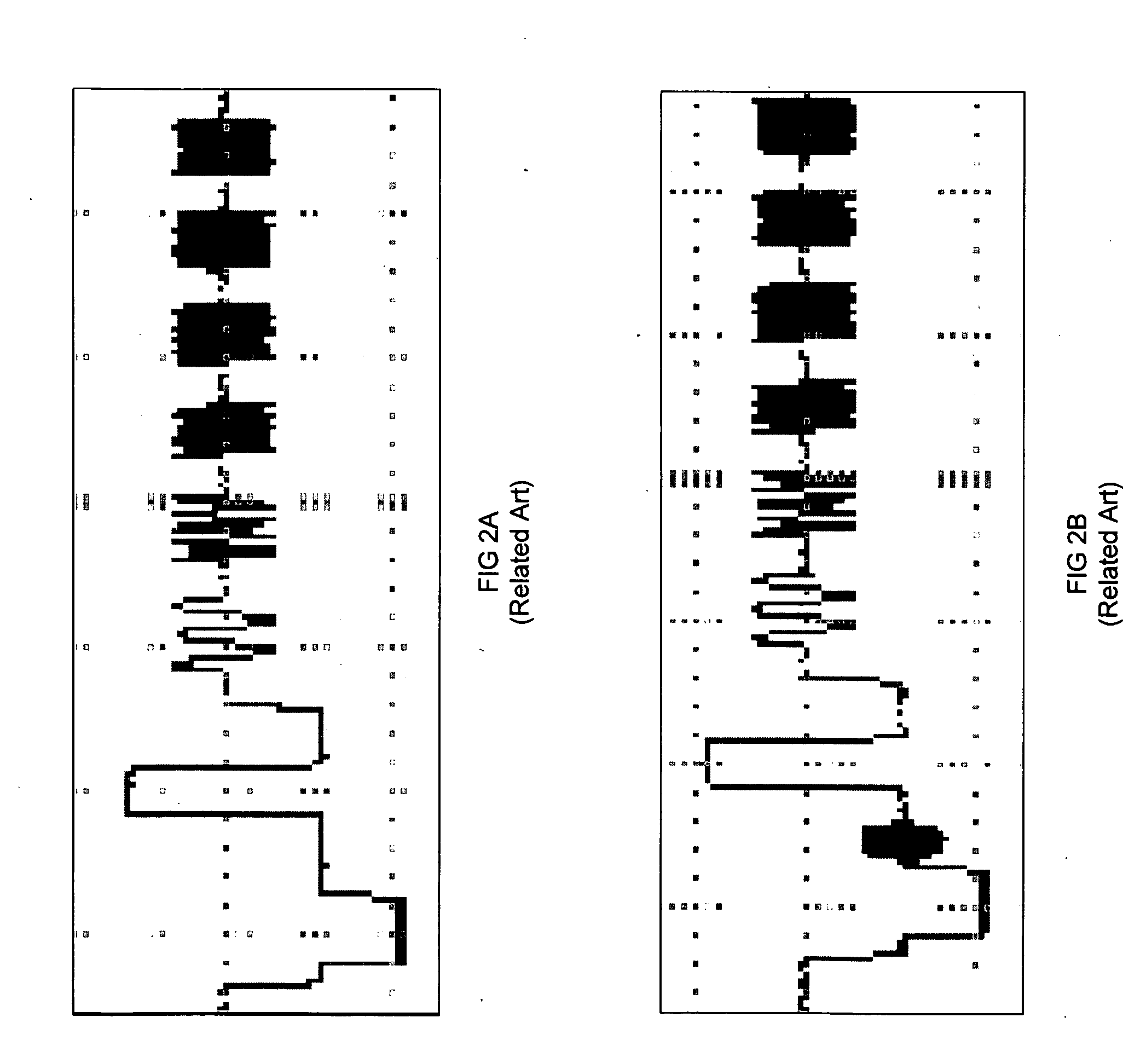
However, and as is common with most other types of transmission lines, a signal becomes increasingly attenuated with increasing transmission line lengths.
As such, conventional methods in which the compensating gain directly correlates only to the length of the transmission line may be inferior to other conventional methods which calculate the precise compensation by measuring the actual attenuation of the signal.
However, conventional adaptive equalizers have a finite limit to the amount of compensation which can be provided.
It has not been believed possible for single chip conventional adaptive equalizers to compensate for losses at sufficiently long transmission line lengths due to the number of internal digital operations which increases the overall signal to noise ratio.
Thus, conventional adaptive equalizers are not suitable for use in UTP receivers where the distance between the UTP receiver and the camera (e.g., the transmission line length) is sufficiently long, for example, greater than 600 meters.
However, such conventional technology unnecessarily wastes power and contributes unnecessary signal noise when any given amplifier stage is enabled but not producing a gain.

Method used


Image

  • Line Tapping Method of Video Amplification for Unshielded Twisted Pair Active Receiver
  • Line Tapping Method of Video Amplification for Unshielded Twisted Pair Active Receiver
  • Line Tapping Method of Video Amplification for Unshielded Twisted Pair Active Receiver

Examples


Embodiment Construction

[0029]The invention, in its various aspects, will be explained in greater detail below with regard to preferred embodiments. While the invention will be described in conjunction with the preferred embodiments, the preferred embodiments themselves do not limit the scope of the invention. Rather the invention, as defined by the claims, may cover alternatives, modifications, and / or equivalents of the preferred embodiments. Similarly, the accompanying drawings do not limit the scope of the preferred embodiments and / or the invention, but rather, are illustrative of one or more examples of the preferred embodiments and / or invention.

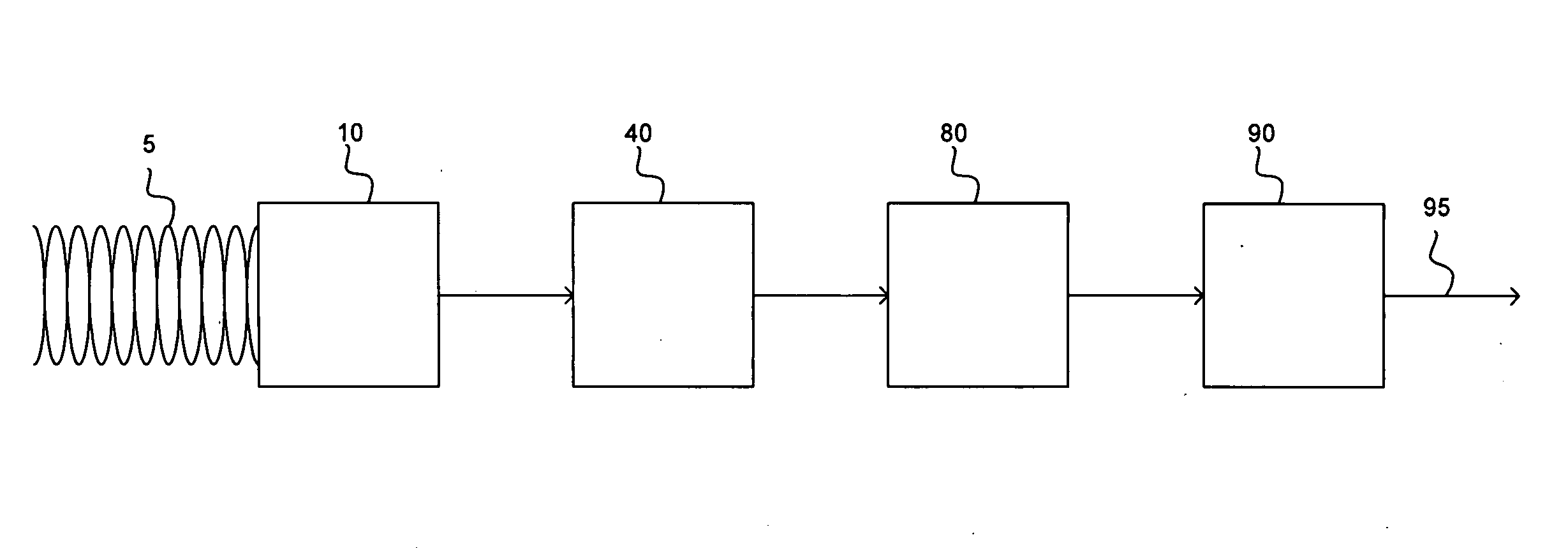
[0030]Referring to the drawings, wherein like reference characters designate like or corresponding parts throughout the several views, and specifically to FIG. 5, embodiments of the present invention can include an electrostatic discharge suppression (ESD) circuit 10, a video amplification circuit 40, and a video driver 90. In some implementations, the video am...


PUM


Abstract

Embodiments of the present invention include systems, methods and apparatus for amplifying a composite video signal transmitted over long distance unshielded twisted pair cabling. The apparatus and system may include a plurality of amplifiers, an analog switch, and a control unit. The control unit generates a configuration signal to enable the output of one or more amplifiers (which may be serially connected) and configure the analog switch. A user input may be provided for manually configuring the amplifiers and analog switch. When the video signal is a color signal, the control unit may automatically configure the amplifiers and analog switch with reference to the amplitude of the color burst.

Description

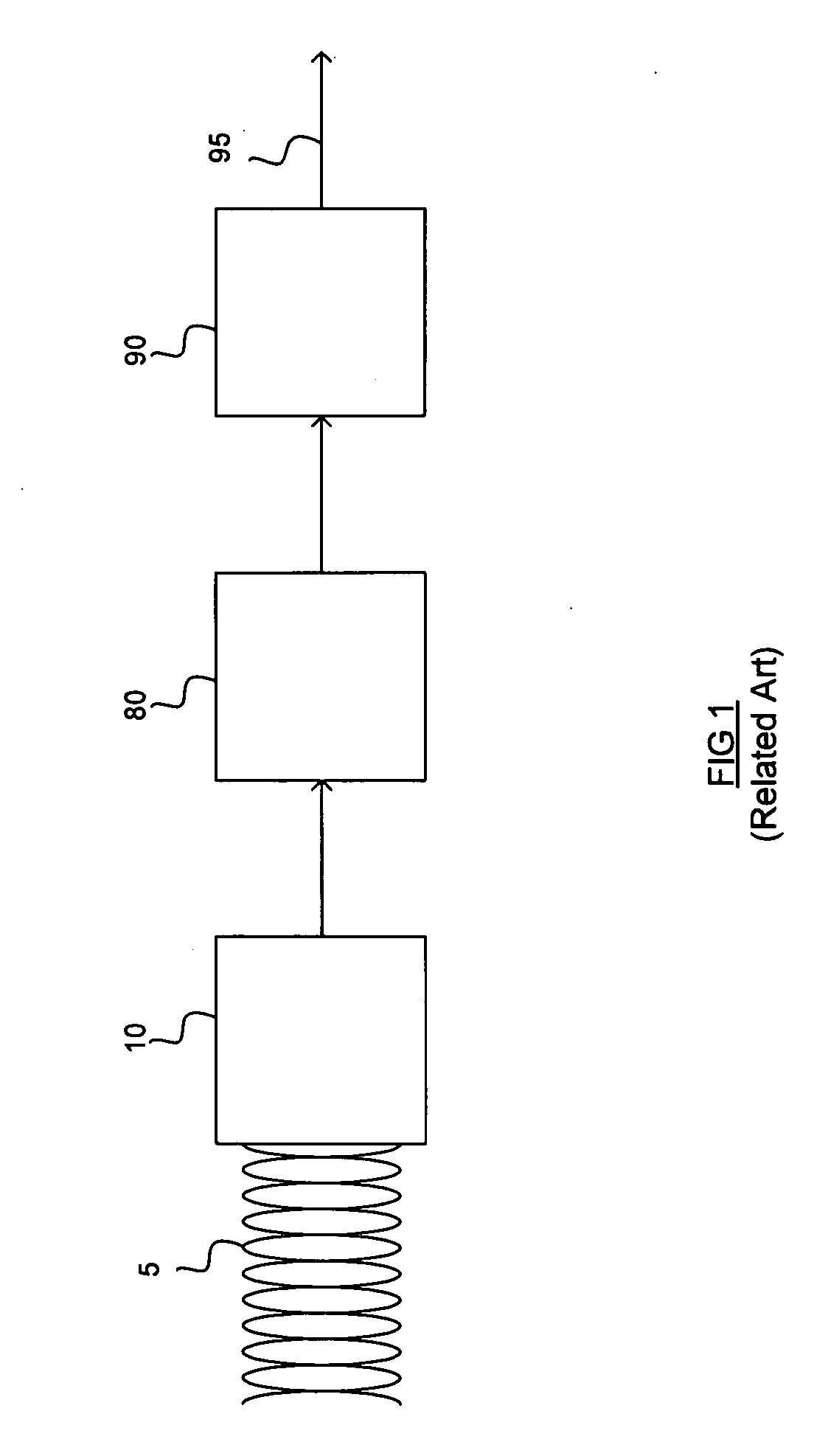
BACKGROUND OF THE INVENTION[0001]1. Field of the Invention[0002]The present invention relates to video signal receivers. More specifically, embodiments of the present invention relate to methods, apparatuses, and systems for amplifying a video signal which has been transmitted over an unshielded twisted pair.[0003]2. Description of the Prior Art[0004]The use of surveillance cameras and related systems is becoming increasingly more prevalent. Not only are surveillance cameras used in such traditional institutions as banks and casinos, but their use has spread to retail and business establishments, indoor and outdoor entry points, airport security checkpoints, government buildings, parking lots, and the like. In most installations, it is desirable to receive images from one or more surveillance cameras in a centralized monitoring location. Depending on the installation, this centralized monitoring location may be several hundred to several thousand meters from any given individual sur...

Claims


Application Information

Patent Timeline
IPC IPC(8): H04N7/16
CPCH04N7/108
Inventor GRIGORIAN, SAMKARKHANIS, YOGITAKOPANHNHA, SOURIKHAN
Owner PELCO INC
Learn More