
Test strip coding and quality measurement

a strip and quality measurement technology, applied in the field of sample analysis system, can solve the problems of reducing manufacturing yield, affecting the reliability of strips, and affecting the quality of strips,

Active Publication Date: 2010-05-11
AGAMATRIX INC
View PDF16 Cites 29 Cited by
  • Summary
  • Abstract
  • Description
  • Claims
  • Application Information

AI Technical Summary

Benefits of technology

This solution enables non-destructive testing of conductive paths, ensures regional or customer-specific compatibility, and enhances manufacturing reliability by allowing for the detection of defects without damaging the strips, while maintaining accurate fluid analysis measurements.

Problems solved by technology

One problem with many test strip designs is that testing of particular conductive paths risks damaging the paths.
With such designs, the very act of testing poses a risk of making the strip less reliable.
Destructive testing then leads to lower manufacturing yields.
This is an undesirable state of affairs.

Method used


Image

  • Test strip coding and quality measurement
  • Test strip coding and quality measurement
  • Test strip coding and quality measurement

Examples


Embodiment Construction

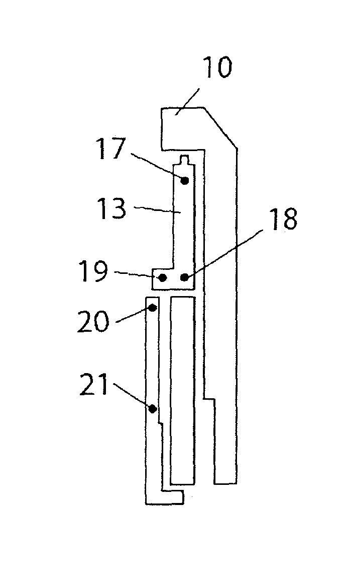
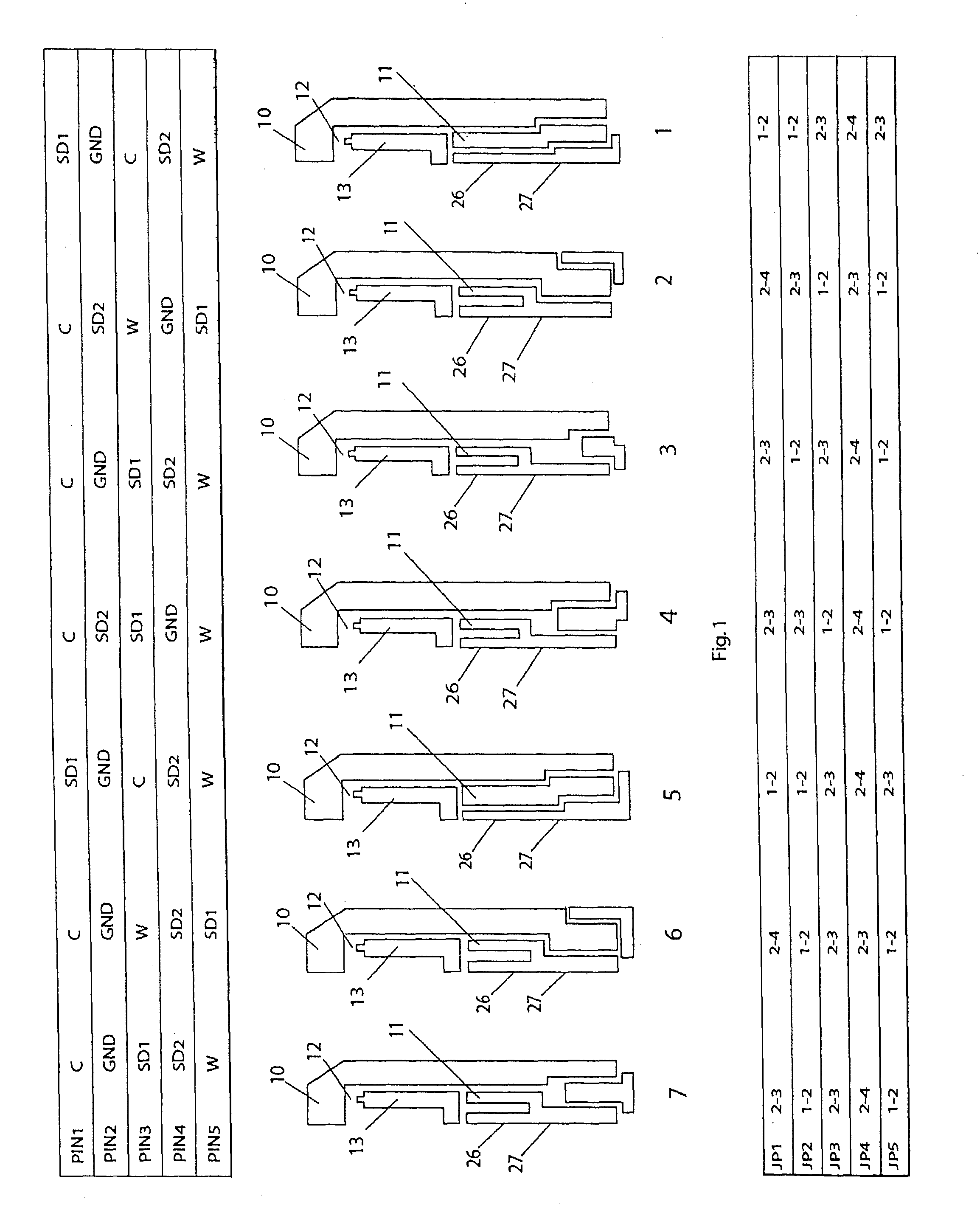
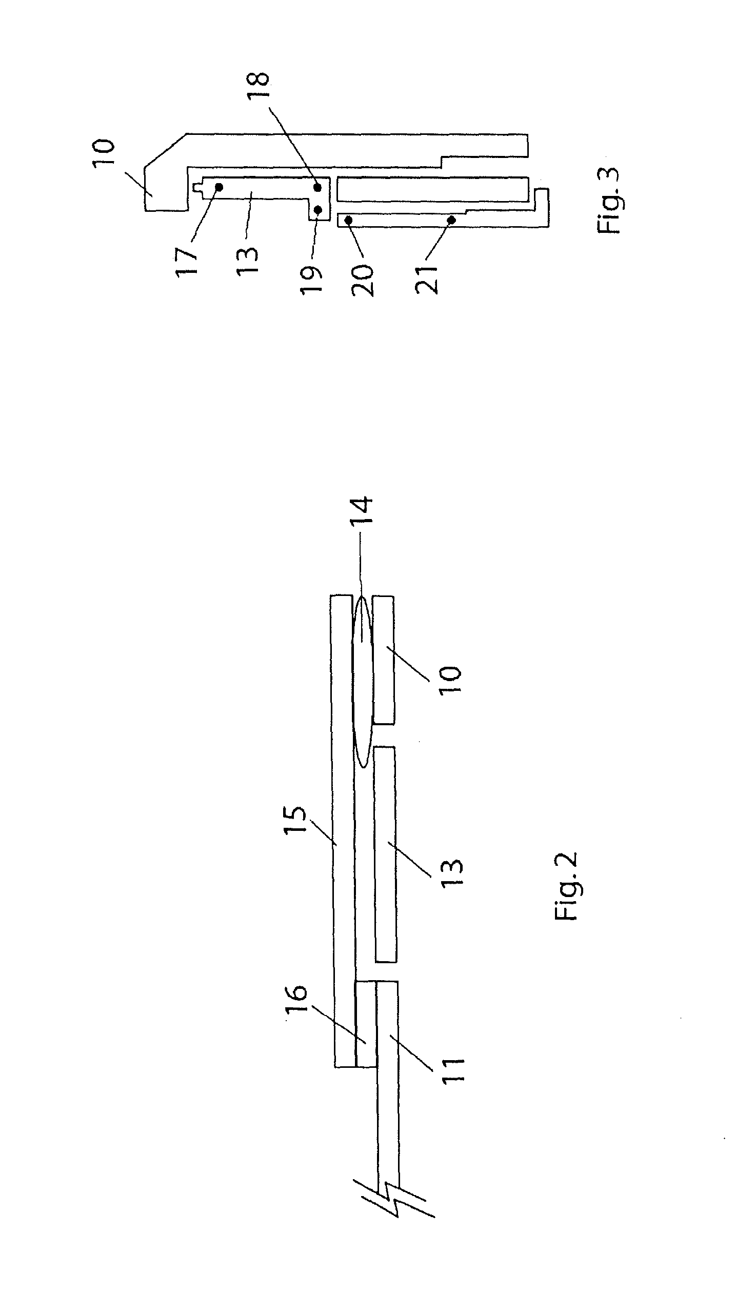
[0016]FIG. 1 shows seven strip configurations in plan view, and also shows pin assignments and jumper assignments. Working electrode areas 10 may be seen as well as counter electrode conduction paths 11. Each strip is elongated with its distal end toward the electrode areas 10 and its proximal end toward the connector area at the other end (toward the bottom of the figure in FIG. 1).

[0017]For each of these configurations, particular pin assignments must be made. The pin assignments appear toward the top of FIG. 1. In each case “C” means the counter electrode, “W” means the working electrode, GND means ground, SD1 means strip detect 1, and SD2 means strip detect 2. Thus for example in the case of configuration 4, it is communicated that the counter electrode connects to the analytical apparatus through connector pin 1, the working electrode connects to the apparatus through pin 5, and so on. This can then be used in connection with circuitry such as that described in copending U.S. a...


PUM

PropertyMeasurementUnit
lengthaaaaaaaaaa
widthaaaaaaaaaa
dimensionaaaaaaaaaa

Abstract

A test strip and analytical apparatus have pin connections permitting the definition of geographic regions or of particular customers. A test strip made for use in a particular region or for a particular customer will have pin connections matching features of the apparatus made for use in that region or by that customer. Insertion of the strip into the apparatus does not merely turn on the apparatus, but provides the regional or customer coding. Analog switches within the apparatus allow coding of a larger number of distinct regions or customers than would otherwise be possible, all without degrading the quality of the measurements made of the fluid being tested. Conductive paths in the strips permit testing the strips during manufacture so as to detect quality lapses regarding the printing or deposition of the paths.

Description

BACKGROUND[0001]The invention relates to a system for analyzing a sample using an electrochemical cell. The electrochemical cell is provided in a test strip. The test strip is elongated and has the cell at one end (sometimes called the “distal” end) and has a connection region at the other end (sometimes called the “proximal” end). The connector region is shaped to plug into a connector on an apparatus. The apparatus contains electronic circuitry for applying signals to the cell and for monitoring signals received from the cell.[0002]The test strip is made up of layers. In an exemplary embodiment the layers are as described in U.S. patent application No. 60 / 521,555 filed May 21, 2004, which application is incorporated herein by reference for all purposes. An elongated substrate or carrier provides mechanical rigidity and support. Deposited or painted onto the substrate are conductive paths such as those shown in FIG. 1 at locations 10, 11, 13. FIG. 1 shows a plan view of one of the ...

Claims


Application Information

Patent Timeline
Patent Type & Authority Patents(United States)
IPC IPC(8): G01N27/327
CPCG01N27/3272B01L3/545B01L3/5023B01L2300/02G01N27/26G01N33/50G01N27/3274
Inventor HARDING, IANIYENGAR, SRIDHARWEI, BAOGUODIAMOND, STEVENFOREST, MARTIN
Owner AGAMATRIX INC
Learn More