One piece ring gear-park brake drum

a brake drum and ring gear technology, applied in the field of metal forming, can solve the problem that the ring gear cannot be machined directly into the parking drum, and achieve the effect of reducing warranty costs, reducing complexity during assembly, and reducing costs

Inactive Publication Date: 2010-04-08
FORD MOTOR CO
View PDF13 Cites 2 Cited by
  • Summary
  • Abstract
  • Description
  • Claims
  • Application Information

AI Technical Summary

Benefits of technology

[0010]The one-piece ring gear-park brake drum is produced at lower cost than the multiple-piece assembly and requires no mechanical connections, welds or bonded connections. Complexity during assembly is greatly reduced compared to the three -piece assembly. Warranty costs are reduced due to few parts and no inter-part connections, which reduce opportunity for in-service component failure. The component is inherently more rigid, lighter and better balanced than a multi-piece assembly.

Problems solved by technology

The ring gear, however, cannot be machined directly into the parking drum because the ring gear must be broached, requiring a long broach bar to pass completely through the ring gear.

Method used


Image

  • One piece ring gear-park brake drum
  • One piece ring gear-park brake drum
  • One piece ring gear-park brake drum

Examples


Embodiment Construction

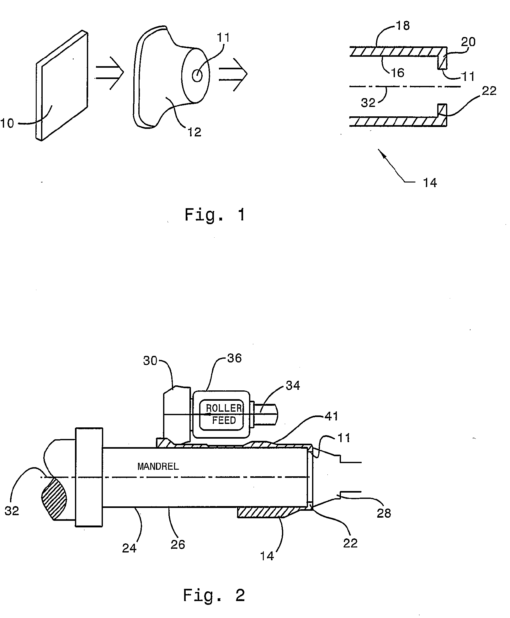
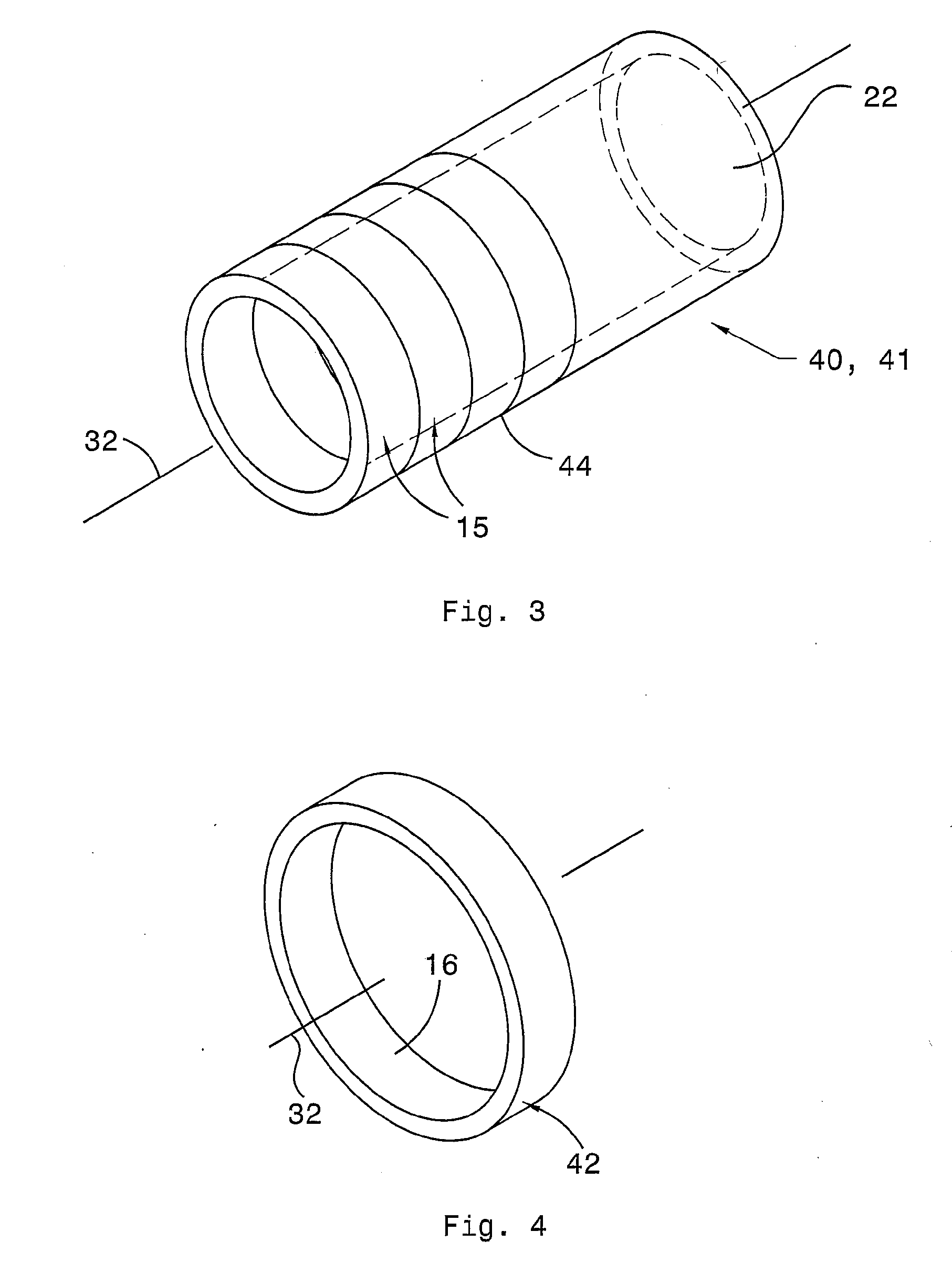
[0027]Referring now to the drawings, FIG. 1 illustrates a workpiece 10, preferably a plate or coiled sheet of carbon steel, which is formed with a central hole 11 into an elongated cup shape 12 by a conventional cold or hot forging or drawing method. After the cupped preform 12 is annealed to soften the material, make it less brittle and relieve internal stresses, the cup shaped preform 12 is processed by various techniques including a flow forming operation to produce a net shape preform 14 having an inner surface 16, an outer surface 18 and an end 20 that is partially closed by a radial flange 22.

[0028]The flow forming procedure illustrated in FIG. 2 employs a mandrel 24 having an exterior surface 26. The net shape preform 14 is fitted over the mandrel and secured at its end 20 by a tailstock 28 that clamps flange 22 to the end of the mandrel. Several rollers 30, mutually spaced angularly about axis 32, are forced into contact with the outer surface of preform 14. Each roller 30 r...


PUM


Abstract

A component for transmitting torque between a gear unit and a shaft includes a ring gear portion, a park brake drum portion formed integrally with the ring gear portion, a disc portion formed integrally with the park brake drum portion, and a hub portion formed integrally with the disc portion.

Description

BACKGROUND OF THE INVENTION[0001]1. Field of the Invention[0002]This invention relates generally to metal forming and, in particular, to an integrated ring gear-parking brake drum produced in one piece from a cold-formed preform. Helical gear teeth are formed on a ring gear portion of the product and spline teeth on a hub portion.[0003]2. Description of the Prior Art[0004]The kinematic arrangement of an automatic transmission for a rear wheel drive motor vehicle may include a Ravigneaux gearset, whose components include two sun gears, a ring gear surrounding the sun gears and two sets of planetary pinions. The pinions of a first set mesh with a first sun gear and the ring gear, the pinions of the second set mesh with a second sun gear and the pinions of the first set. The transmission output torque is carried by the ring gear, transmitted axially by a parking drum to a radial disc and transmitted radially to a sleeve or hub, which is connected by a spline to the transmission output ...

Claims


Application Information

Patent Timeline
Patent Type & Authority Applications(United States)
IPC IPC(8): F16H57/10
CPCF16D65/10Y10T74/19637F16H63/3425
Inventor SZUBA, JOSEPHWHITBECK, RODNEY G.
Owner FORD MOTOR CO
Why Eureka
Try Eureka