Acoustic Drum With Resonators Disposed Therein

Inactive Publication Date: 2010-04-08
PEAVEY ELECTRONICS
View PDF34 Cites 29 Cited by
  • Summary
  • Abstract
  • Description
  • Claims
  • Application Information

AI Technical Summary

Benefits of technology

[0007]Among the objects of the present invention is

Problems solved by technology

The mass of the relatively thick shell and the mass of the metal lugs tended to significantly dampen the resonance of the drum system.
Conventional drums today are of very similar construction and operation as the drums of the 1800s (

Method used


Image

  • Acoustic Drum With Resonators Disposed Therein
  • Acoustic Drum With Resonators Disposed Therein
  • Acoustic Drum With Resonators Disposed Therein

Examples


Example

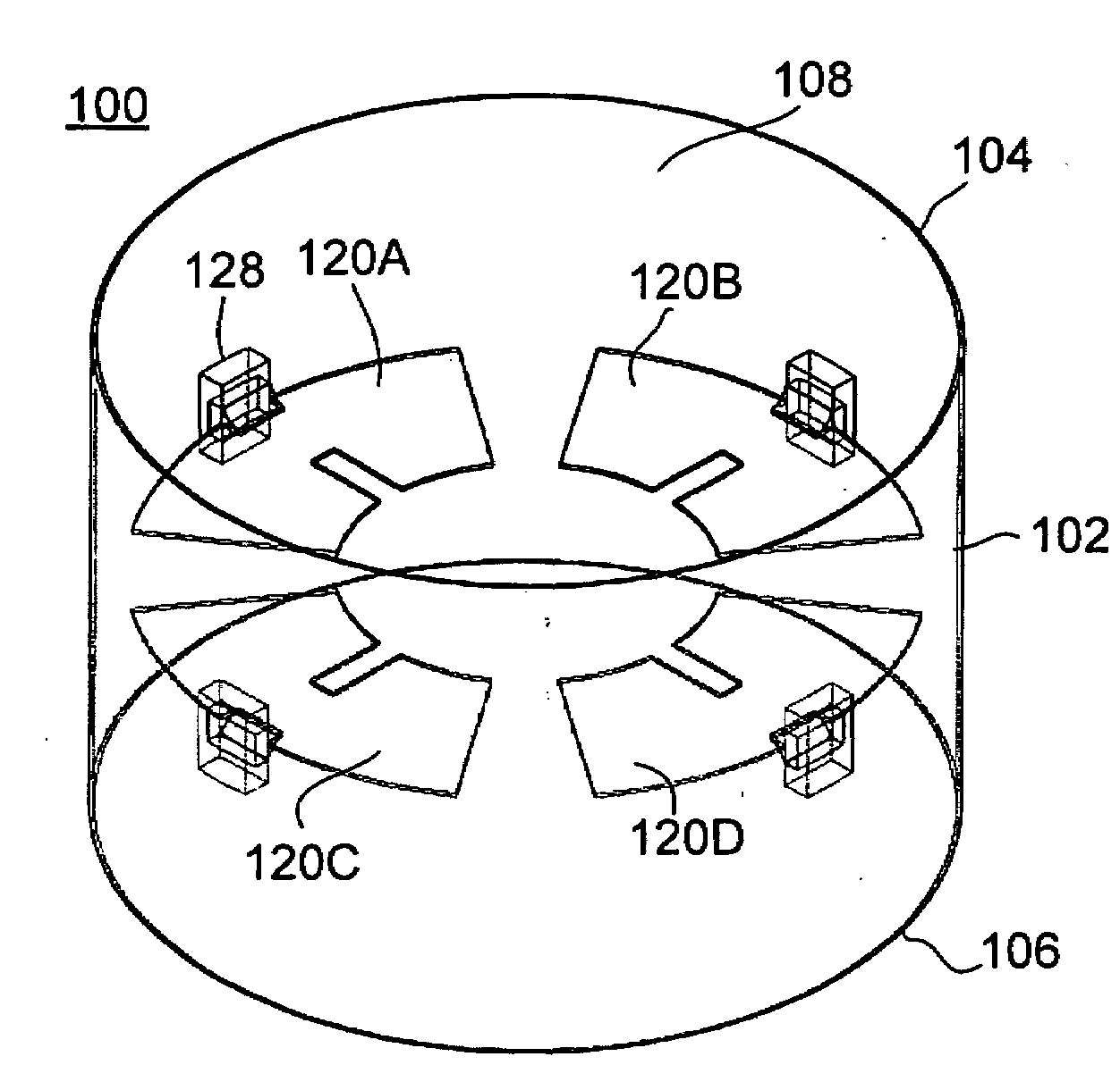
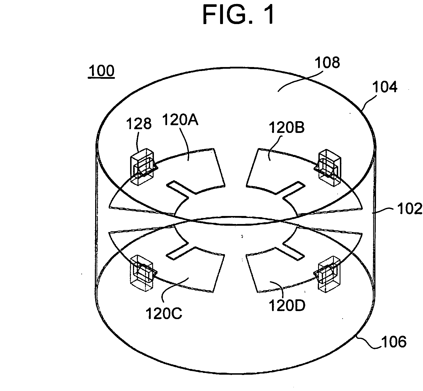
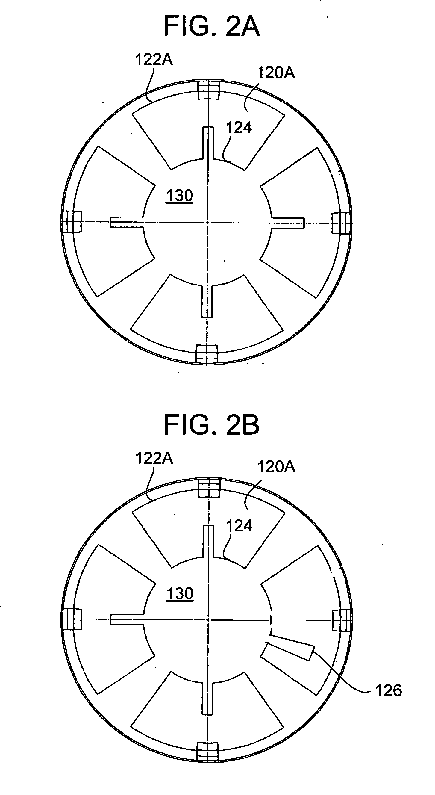
[0029]With reference to the drawings, wherein like numerals indicate like elements, there is shown in FIGS. 1-2A a drum 100. The drum 100 includes a shell 102 having first and second, spaced apart ends 104, 106, and an interior surface 108 defining an interior volume 110. As best seen in FIG. 3, a drumhead 24 may be stretched over the first end 104 of the shell 102 and secured using a rim 26 and bolts 28. The rim engages a bead 25 of the drumhead 24 in order to even stretch the drumhead 24 over the first end 104 of the shell 102. Although not required, a second drumhead (not shown) of the same or similar construction as the drumhead 24 may be employed and stretched over the second end 106 of the shell 102.

[0030]One or more resonators 120A, 120B, 120C, 120D, are coupled to the inside surface 108 of the shell 102. In particular each resonator 120 is coupled at one edge (for example, edge 122A) thereof in lever fashion to the interior surface 108 of the shell 102. The drum 100 may incl...


PUM


Abstract

An acoustic drum includes: a shell having first and second, spaced apart ends, and an interior surface defining an interior volume; a drumhead stretched over the first end of the shell; and at least one resonator coupled at one edge in lever fashion to the interior surface of the shell, the at least one resonator being sized and shaped to resonate at a frequency proximate to a peak resonant frequency of the drum.

Description

BACKGROUND OF THE INVENTION[0001]The present invention relates to an acoustic drum having a resonator therein, which is operable to improve the resonant characteristics of the drum.[0002]Essentially, a drum is the simplest musical instrument, comprising an enclosure or shell of some kind, and a membrane (or head) stretched over an opening of the shell. The operational principle of drums are fairly simple, they are resonant systems, essentially Helmholtz resonators. Energy is imparted to the head by striking it with some type of object, such as a stick, mallet or a player's hand. The energy imparted to the head activates air inside the shell of the drum, thereby creating a resonant effect, which is recognizable as what is generally referred to as a drum beat.[0003]Modern drums emerged in the late 1800s, and included a shell and one or two heads that were secured to the drum shell by a wooden or metal rim (or hoop) that served to fasten and tension the head to the shell. Machine screw...

Claims


Application Information

Patent Timeline
IPC IPC(8): G10D13/02G10D13/22
CPCG10D13/021G10D13/02G10D13/22G10D13/25
Inventor PEAVEY, HARTLEY D.
Owner PEAVEY ELECTRONICS
Why Eureka
Try Eureka