Inhalation device and heating unit therefor

a technology of inhalation device and heating unit, which is applied in the direction of inhalators, other medical devices, tobacco, etc., can solve the problems of complicated technical measures, insufficient stability of flames in combustion chambers, and significant differences in the handling of known inhalation devices

Inactive Publication Date: 2010-04-08
SILLER FRIEDRICH
View PDF21 Cites 335 Cited by
  • Summary
  • Abstract
  • Description
  • Claims
  • Application Information

AI Technical Summary

Problems solved by technology

Concerning the prior art, it is considered disadvantageous that the handling of the known inhalation devices differs significantly from the conventional handling of a cigarette as known to a smoker, that the flame does not burn in the combustion chamber with sufficient stability, and / or that stabilization of the combustion process requires complicated technical measures.

Method used


Image

  • Inhalation device and heating unit therefor
  • Inhalation device and heating unit therefor
  • Inhalation device and heating unit therefor

Examples


first embodiment

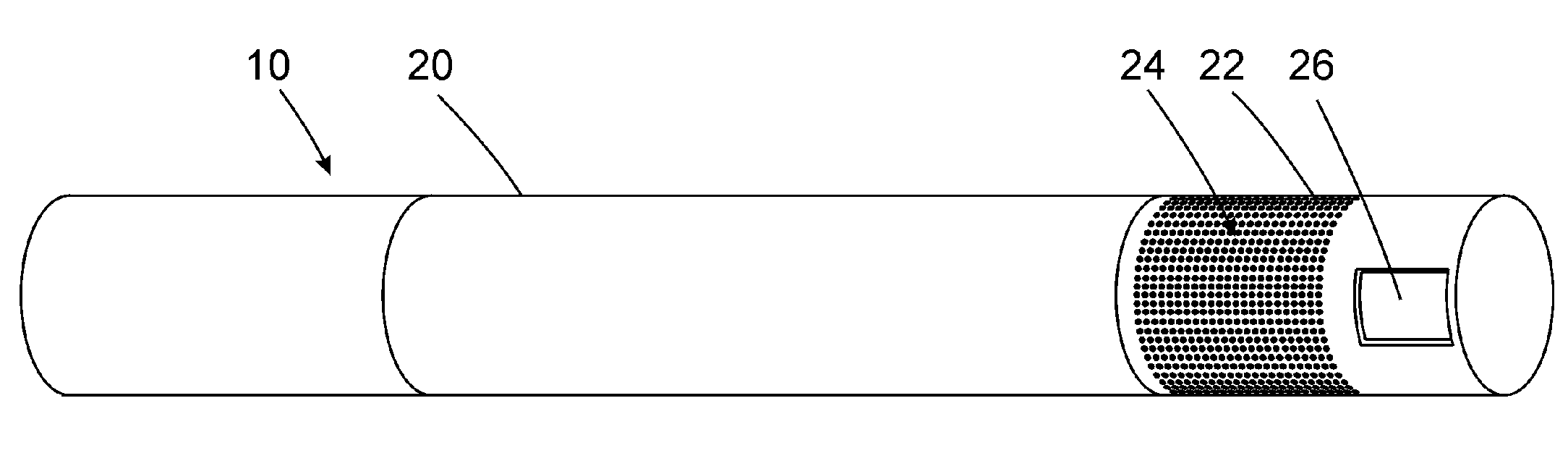
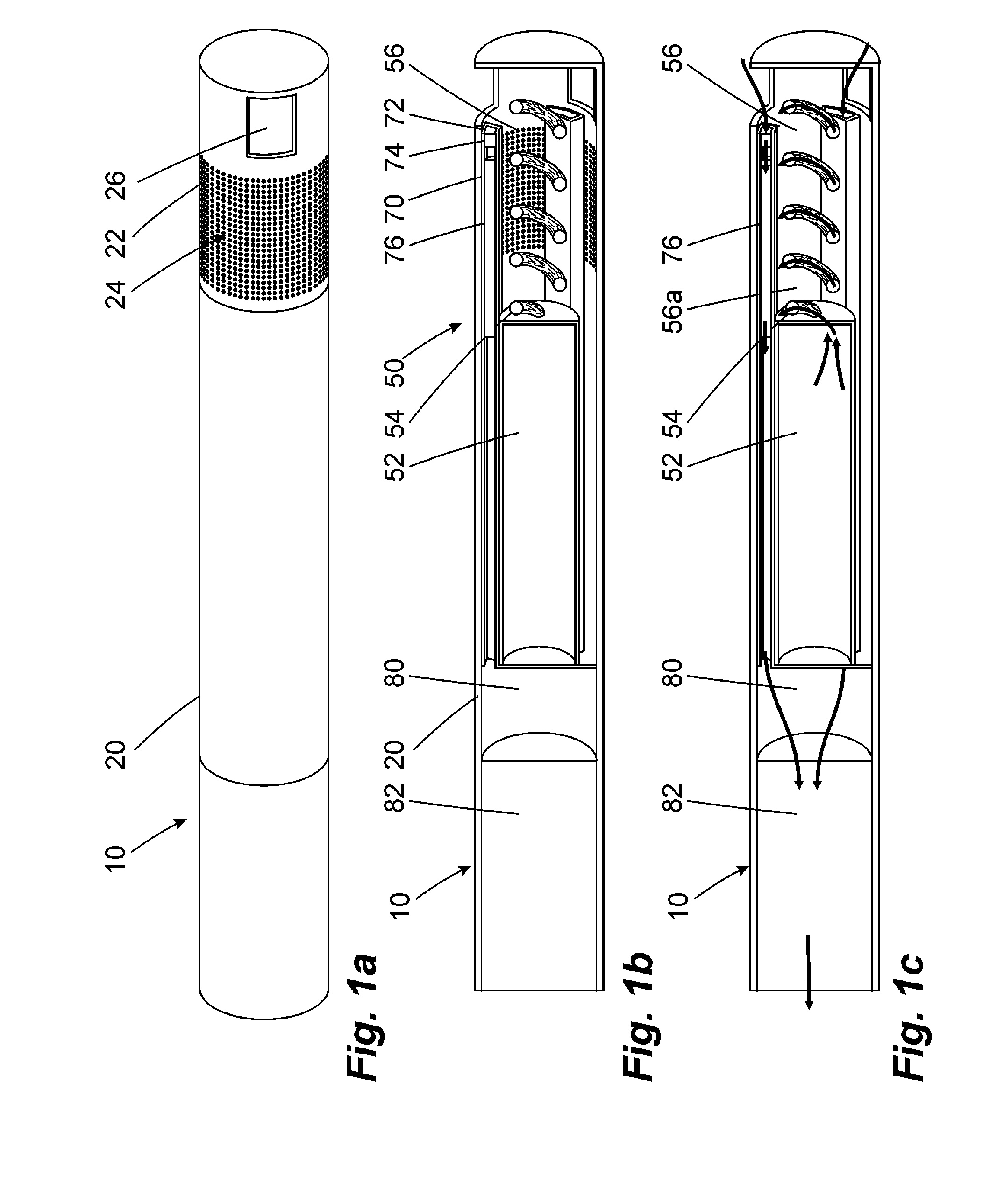
[0058]FIGS. 1a to 1c show an inventive inhalation device 10. It is of cylindrical design and has an outside wall 20 that is provided with micro openings 24 at a distal end of the inhalation device 10 as combustion chamber wall 22. The wall 20 has a recess 26 at the distal end face.

[0059]FIG. 1b shows the inside construction of the inhalation device 10. A heating unit 50 is provided at the distal end of the inhalation device 10. The heating unit has a fuel storage 52 in which the fuel is stored in a liquid state. A wick 54 extends from the fuel storage 52 into a combustion chamber 56 that is provided at the distal end of the inhalation device and that is surrounded by the combustion chamber wall 22. The wick 54 is formed like a screw. A total of three inhalation mixture generators 70 are arranged on an inside of the outside wall 20 distributed over the circumference and each extends essentially axially starting from the distal end of the inhalation device in the direction of the prox...

second embodiment

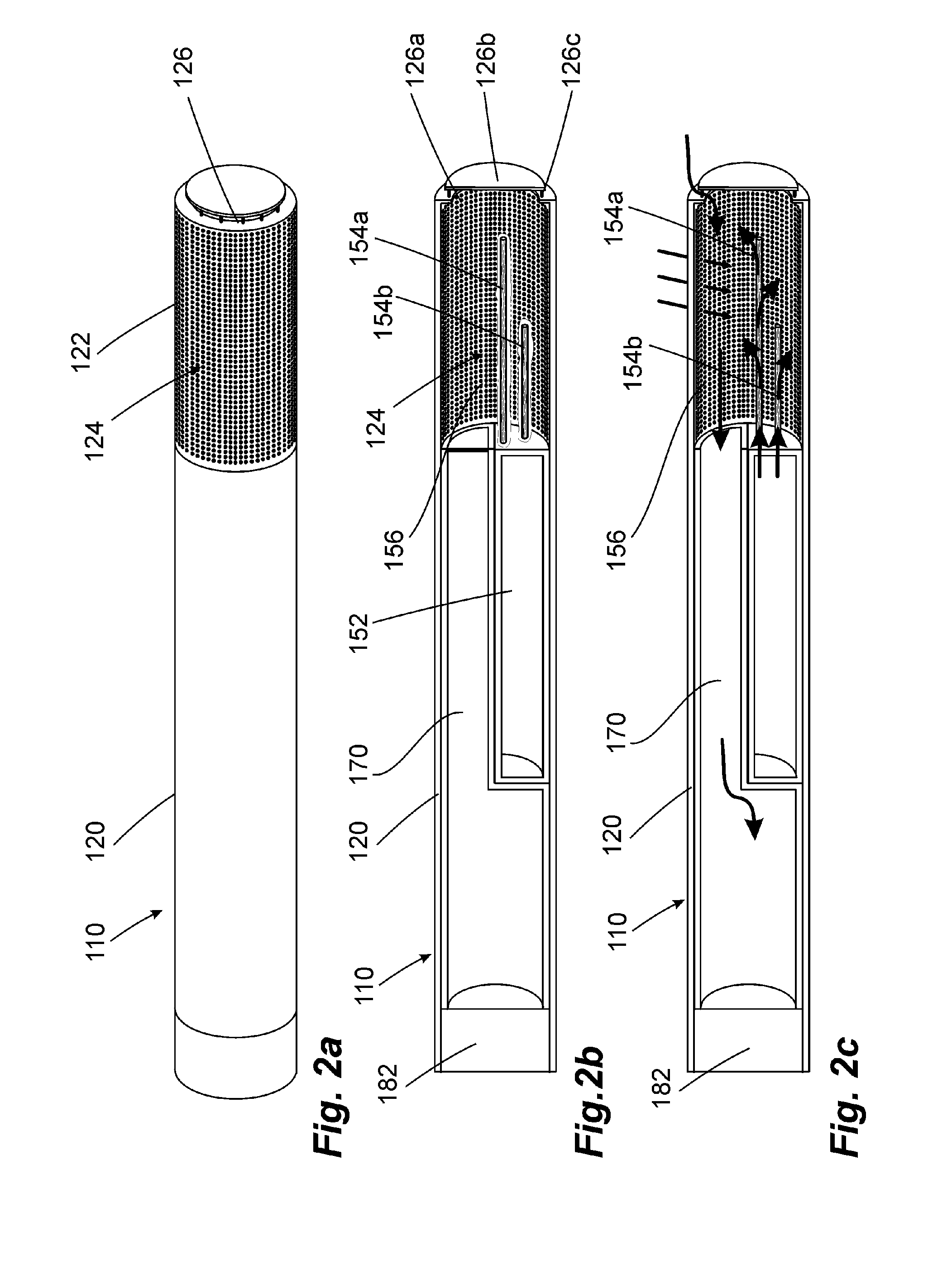
[0064]FIGS. 2a to 2c show an inventive inhalation device. In many regards this inhalation device 110 is similar to the embodiment of FIG. 1. If nothing else is specified below, its method of operation is the same.

[0065]The inhalation device 110 exhibits an outside wall 120 whose front end is designed as combustion chamber wall 122. A fuel storage 152, a combustion chamber 156, and an inhalation mixture generator 170 are provided inside this outside wall 120.

[0066]The arrangement of the inhalation mixture generator 170 and of the fuel storage 152 deviates from the embodiments of FIG. 1. While the inhalation mixture generator 170 occupies the entire cross section in the rear area of the inhalation device 110, the cross section splits into two semi-circular cross sectional areas in the central area of the inhalation mixture generator 170, the one being occupied by the fuel storage 152 and the other by the inhalation mixture generator 170. This simplified design is advantageous with reg...

third embodiment

[0071]A third embodiment can be gathered from FIGS. 3a to 3c. The inhalation device 210 that has been illustrated has a cylindrical shape with a jacket shaped outside wall 220. It is closed at the distal end by a cup shaped fuel storage 252 of chromium-nickel spring steel, the fuel storage 252 containing a fuel 258 of a gel-like consistency and being open in the direction of a combustion chamber 256. Before starting the inhalation device 210, the open side of the fuel storage 252 is closed, as can be seen in FIG. 3b, by a membrane 260 made from a material of low elasticity, for example an aluminum foil.

[0072]The combustion chamber 256 is surrounded by micro openings 224 in a combustion chamber wall section 222 of the outside wall 220. An ignition access 226 is additionally provided on one side and comprises a total of four elongate apertures between which only narrow webs are provided. An inhalation mixture generator 270 adjoins the combustion chamber 256 on the proximal side and is...


PUM


Abstract

The invention relates to a heating unit for an inhalation device for the inhalation administration of an inhalation mixture of air and at least one additive material, having a fuel storage (252) which is filled or can be filled with a thermally combustible solid or liquid fuel (258), and with a combustion chamber (256) for the combustion of the fuel (258), which is essentially sealed from the surroundings by a combustion chamber wall (222). The invention further relates to an inhalation device (210) with such a heating unit.
According to the invention, the combustion chamber (256) is designed for forming a flame, and the combustion chamber wall (222) has at least some micro openings (224). The micro openings are designed in such a way that the sum of the outer side lengths of all micro openings (224) is at least 140 mm, and the sum of the outer side lengths of the micro openings (224) per surface in the area of the combustion chamber wall (222) averages at least 80 mm/cm2.
Application as cigarette substitute or as aid for nicotine withdrawal.

Description

TECHNICAL FIELD[0001]The invention relates to a heating unit for an inhalation device for the inhalation administration of an inhalation mixture of air and at least one additive material, having a fuel storage which is filled or can be filled with a thermally combustible solid or liquid fuel, and with a combustion chamber for the combustion of the fuel, which is essentially sealed from the surroundings by a combustion chamber wall. The invention further relates to an inhalation device for the inhalation administration of an inhalation mixture of air and at least one additive material with a mouthpiece, an inhalation mixture generator with an air inlet opening, and a heating unit for the combustion of a fuel and for heating the air and / or the additive material and / or the inhalation mixture, the inhalation mixture generator being directly connected to the mouthpiece or via an inhalation duct.BACKGROUND OF THE INVENTION[0002]Generic inhalation devices are known in the prior art. The in...

Claims


Application Information

Patent Timeline
Patent Type & Authority Applications(United States)
IPC IPC(8): A61M15/06A24F42/10A24F42/60
CPCA24F47/006A61M11/047A61M15/06A61M11/041A61M11/048A24F42/10A24F42/60A61M2205/364
Inventor SILLER, FRIEDRICH
Owner SILLER FRIEDRICH
Why Eureka
Try Eureka