RFID system, reader-writer, and RFID tag

Active Publication Date: 2010-04-08
RAKUTEN GRP INC
View PDF6 Cites 21 Cited by
  • Summary
  • Abstract
  • Description
  • Claims
  • Application Information

AI Technical Summary

Benefits of technology

[0009]Another object of the invention is to prevent the reading-completion flag from erroneously being set to the reading-completion state.
[0020]Another object of the invention is to provide a reader-writer that can prevent a non-read REID tag from remaining when plural unspecified RFID tags exist in a range where the RF waves of the reader-writer arrive.

Problems solved by technology

Accordingly, when response signals in the same RF band from the plural RFID tags collide with each other, or the like, only the response signal having the highest signal level was read and thus it was difficult to read all the RFID tags.
Therefore, when the reading could not be made at a predetermined time to read, there is a problem that a non-read RFID tag which is permanently not detected remains.

Method used


Image

  • RFID system, reader-writer, and RFID tag
  • RFID system, reader-writer, and RFID tag
  • RFID system, reader-writer, and RFID tag

Examples


first embodiment

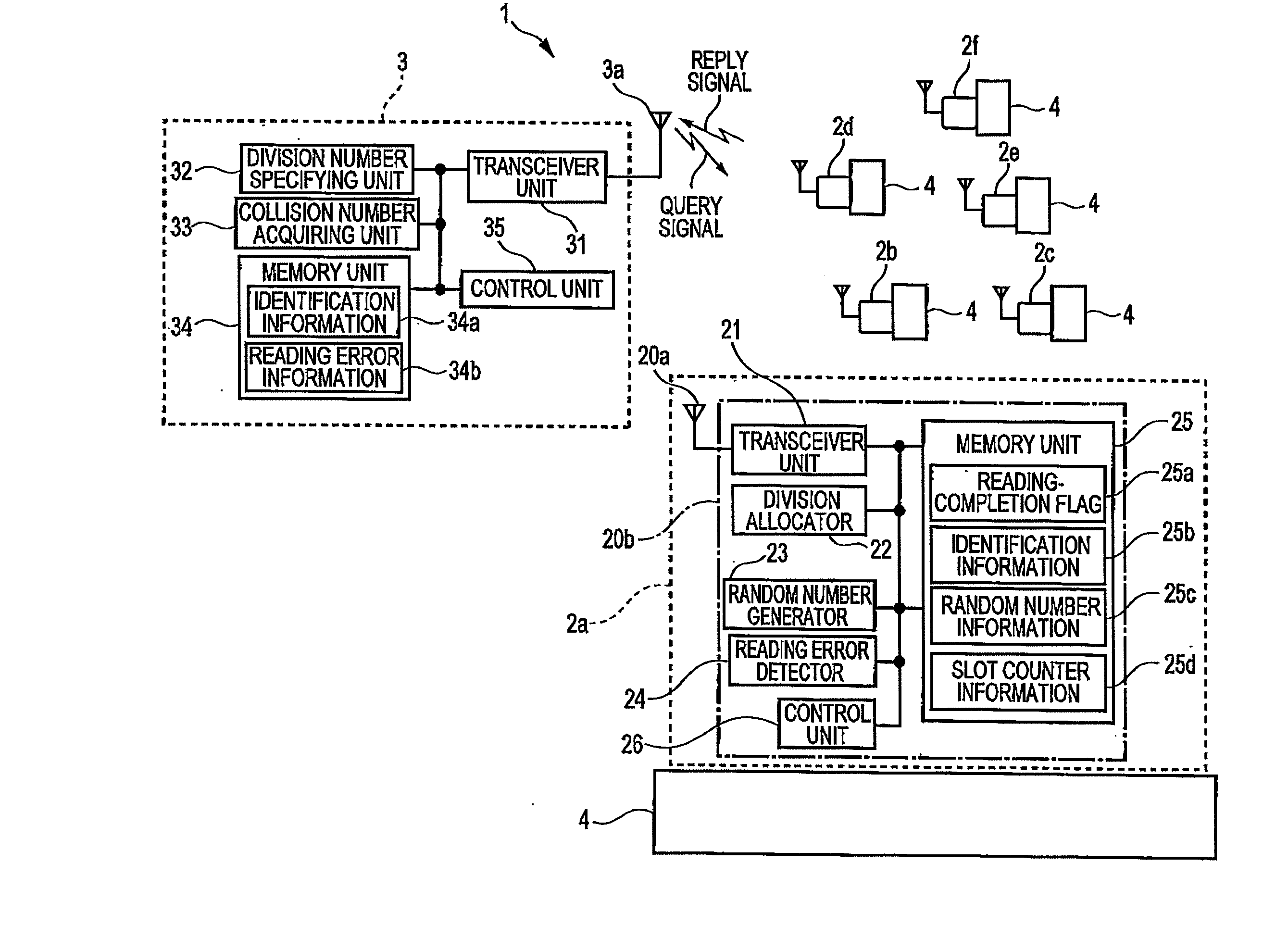
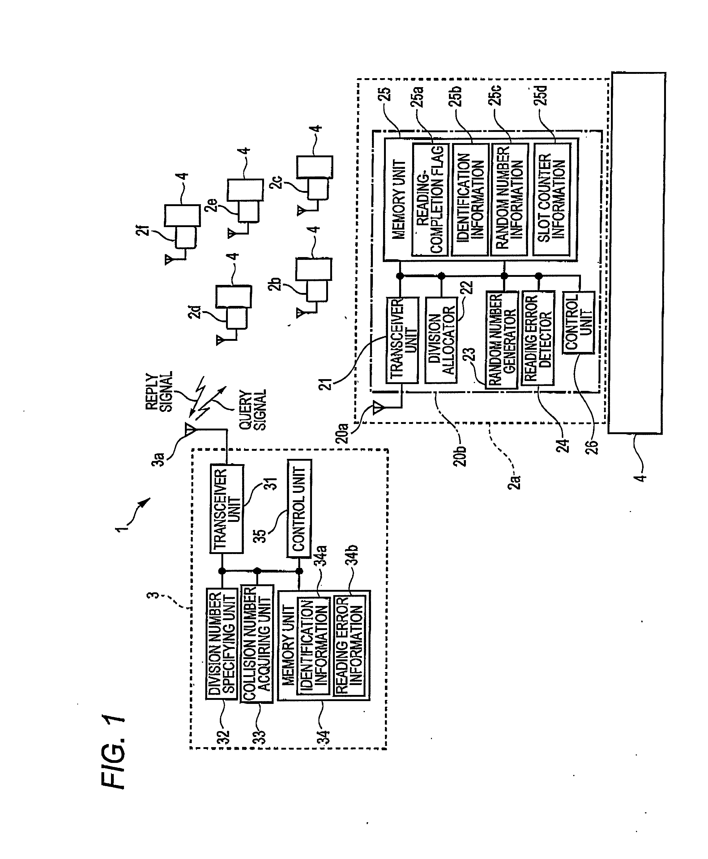
[0039]The entire configuration and operations of an RFID system 1 according to a first embodiment of the invention will be first described with reference to FIG. 1.

[0040]FIG. 1 is a diagram schematically illustrating an RFID system 1 according to a first embodiment of the invention. For example, products stored and managed in a storehouse or the like are described here as managing articles 4. In the storehouse, plural managing articles 4 are loaded by palettes or the like and carried by fork lifts from unspecified places. Since the plural managing articles 4 are forwarded to unspecified places, the management is very troublesome. In the first embodiment, as shown in FIG. 1, RFID tags 2a to 2f are attached to the managing articles 4 and the managing articles are managed by the RFID system 1 by reading the RFID tags 2a to 2f by the use of a reader-writer 3.

[0041]In this way, the RFID system 1 includes the RFID tags 2a to 2f and the reader-writer 3. For the purpose of easy understandin...

second embodiment

[0108]In a second embodiment of the invention, a processing time to read the identification information of the RFID tags is reduced in the RFID system according to the first embodiment.

[0109]The entire configuration and operation of the RFID system 1 according to the second embodiment of the invention will be described now with reference to FIG. 5. The same reference numerals and signs as the first embodiment reference the same elements and description thereof is omitted.

[0110]FIG. 5 is a diagram schematically illustrating the configuration of an RFID system 1 according to the second embodiment of the invention.

[0111]A presence signal transmitter 124 transmits a presence signal. The presence signal is used to inform the reader-writer 3 whether the RFID tags 2 to be read exist in a communication area and does not require a data part or authentication information. Accordingly, a reply signal not including the data part or the authentication information is returned as the presence sign...

third embodiment

[0177]In a third embodiment of the invention, a decrease in reading efficiency is suppressed even when a new RFID tag is added in a predetermined communication area in the RFID system according to the first embodiment.

[0178]The entire configuration and operation of the RFID system 1 according to the third embodiment of the invention will be described now with reference to FIG. 9.

[0179]FIG. 9 is a diagram schematically illustrating the configuration of the RFID system 1 according to the third embodiment of the invention. The same reference numerals and signs as FIG. 1 according to the first embodiment reference the same elements and description thereof is omitted.

[0180]An auxiliary flag 224 is a flag holding operation information of the reading-completion flag 25a for a predetermined time. The setting of the auxiliary flag 224 will be described later.

[0181]A reading-completion flag 25a, identification information 25b, random number information 25c, and slot counter information 25d ar...


PUM


Abstract

An object of the invention is to prevent a non-read RFID from remaining even when plural unspecified RFID tags exist in a range where RF waves of a reader-writer arrive.An RFID system includes: a plurality of RFID tags each having a tag antenna unit and a tag circuit unit storing identification information; and a reader-writer including a first transceiver unit reading the identification information of the plurality of RFID tags using an antenna. Here, when the identification information to be read is not read from one of the plurality of RFID tags due to an occurrence of a reading error in the first transceiver unit after a reading command for reading the identification information is transmitted via the antenna from the first transceiver unit, the reader-writer adds reading error information, which states that the reading error occurs, to the reading command to be transmitted next and transmits the resultant command from the first transceiver unit via the antenna. According to this configuration, it is possible to prevent a non-read RFID from remaining even when plural unspecified RFID tags exist in a range where RF waves of a reader-writer arrive.

Description

BACKGROUND[0001]1. Field of the Invention[0002]The present invention relates to an RFID system, a reader-writer, and an RFID tag.[0003]2. Description of the Related Art[0004]In recent years, RFID (Radio Frequency IDentification) tags having predetermined identification information given thereto were widely used and RFID systems for managing production, physical distribution, products, and the like were suggested. The RFID system includes RFID tags attached to plural products and a reader-writer, reading the identification information of the RFID tags (for example, see Patent Document 1).[0005]Patent Document 1: JP-A-2006-238381[0006]In known RFID systems, when the reader-writer transmits a reading command, plural unspecified RFID tags existing in a range where RF waves arrive respond at a time. Accordingly, when response signals in the same RF band from the plural RFID tags collide with each other, or the like, only the response signal having the highest signal level was read and th...

Claims


Application Information

Patent Timeline
IPC IPC(8): H04Q5/22G08B13/14
CPCH04Q9/00H04Q2209/86H04Q2209/47
Inventor SUEOKA, TOSHIO
Owner RAKUTEN GRP INC
Why Eureka
Try Eureka