Method and a plant for producing articles, in particular paper rolls or the like, and a conveying apparatus usable in said plant

a technology for conveying equipment and articles, which is applied in the field of method of operation of a plant for producing, conveying and packaging articles, can solve the problems of insufficient utilization of the high working rate potential of the above-mentioned known machines, low actual yield of the production plant, and inability to achieve the effect of high working rate potential, reducing the number of personnel assigned, and preventing erroneous system settings

Inactive Publication Date: 2005-06-21
PULSAR SRL
View PDF31 Cites 10 Cited by
  • Summary
  • Abstract
  • Description
  • Claims
  • Application Information

AI Technical Summary

Benefits of technology

[0052]The present architecture of the “system” for controlling the plant allows to use work machines having a complex operation which is managed directly by the local control units of the individual operative sections. According to the present invention, co-ordination between said operative sections and the conveyance line is obtained by providing a central control unit, presenting a simplified programming aimed at determining data for controlling the individual sections of the plant, which are sent to the respective sections, avoiding the need to take into account the specific and internal operation of the various operative sections. It is therefore possible to co-ordinate, in a plant for producing rolls, the operation of known machines produced by the most disparate manufacturers, obtaining a desired operation of the plant thus obtained.
[0053]It is thereby possible to co-ordinate in extremely short times, for instance on the occasion of the change in the formats of the packs to be packaged or of the rolls to be manufactured, the operation of the upstream operative section and of the downstream operative section, with the apparatus for conveying the articles. Among other advantages, such co-ordination prevents erroneous system settings. Operating stoppages, with the related production losses and machinery wear, are minimized. It is also possible to reduce the number of personnel assigned to such machines and the risks of erroneous settings deriving from mistakes by said personnel.

Problems solved by technology

In plants according to the prior art and in particular in plants that employ machines produced by different manufacturers, however, there is a problem with coordinating the operation between the roll forming machines and the packaging machines, as well as between the packaging machines and the conveyor belts connecting them, which causes the actual yield of the production plants to be quite low and does not allow sufficiently to exploit the high working rate potential of the aforesaid known machines.
Such a way of proceeding, which entails an adjustment of the system that could be defined of the “manual” kind, is, however, quite unproductive.
It is not at all easy for the operators, who generally do not have a very high education level, to obtain a proper adjustment of the system, especially when it is necessary to manage several format changes and the operators of the various machines have difficulties communicating with each other.
This also takes place in consideration of the fact that the plants present considerable dimensions and there is an objective difficulty in communicating, also because of the noise in the plants, and in moving between the densely spaced lines for conveying the articles.
Such a local adjustment of the operation of each individual machine in the system usually leads to an incorrect operation of the system.
Therefore, even in the presence of machines that are able to operate at high speeds, one actually obtains rather modest production rates, which frustrate the heavy financial investment needed to purchase such high speed machines.
Moreover, this way of operating, which ultimately entails numerous stops of the upstream shearing or forming machine, as well as of the packaging machine, is quite harmful to the duration of their working life.
The components of said machines are subjected to continuous accelerations and decelerations needed to bring them from the operating condition to the stopped condition, which induce stresses that, in the long term, lead to failures and wear of the main mechanical parts of the machines.
The stops, due to emergency causes, of said circular blade, can, over time, damage the actuating mechanism of the blade, with considerable repair costs and production losses due to the machine idle time.
In traditional plants for articles, such as said rolls, the risk that the articles may be upset is high and the consequent plant stop causes production losses and, over time, the failure and wear of the mechanical parts of the parts employed.
Obviously, for short rolls with large diameters the risk of upsetting is greater.
Therefore, making the upstream shearing machine operate at the maximum working rate aggravates the risk of upsetting the articles, at least in relation to certain types of products, such as the aforesaid rolls with reduced length.
It should also be noted that, in known plants, rolls can be damaged, during their transfer, by excessively high conveyance speeds, especially due to the contact of the rolls themselves with the conveying guides.

Method used


Image

  • Method and a plant for producing articles, in particular paper rolls or the like, and a conveying apparatus usable in said plant
  • Method and a plant for producing articles, in particular paper rolls or the like, and a conveying apparatus usable in said plant
  • Method and a plant for producing articles, in particular paper rolls or the like, and a conveying apparatus usable in said plant

Examples


first embodiment

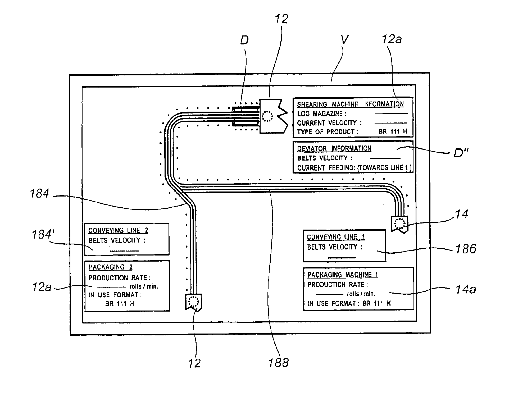
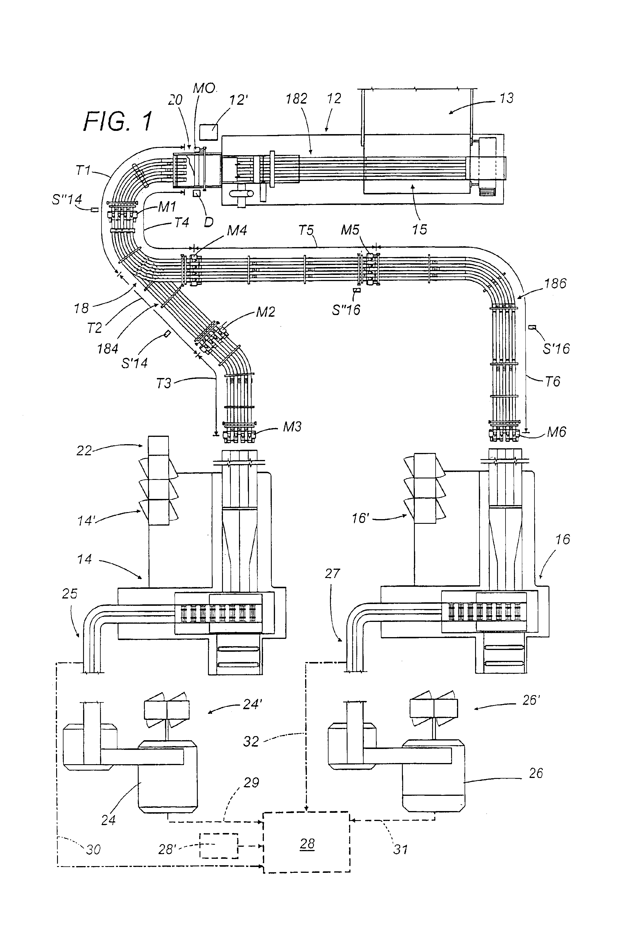
[0065]FIG. 1 illustrates a plant according to the present invention. The plant of this figure comprises a preferred embodiment of apparatus for conveying articles between an operative section positioned upstream 12 and a first and a second operative sections 14, 16 positioned downstream.

[0066]In particular, said upstream operative section is a machine 12 for forming rolls of paper material or the like starting from individual logs or elongated coils (not shown in the accompanying figures) and said downstream working sections are machines 14, 16 for packaging said articles into respective packs.

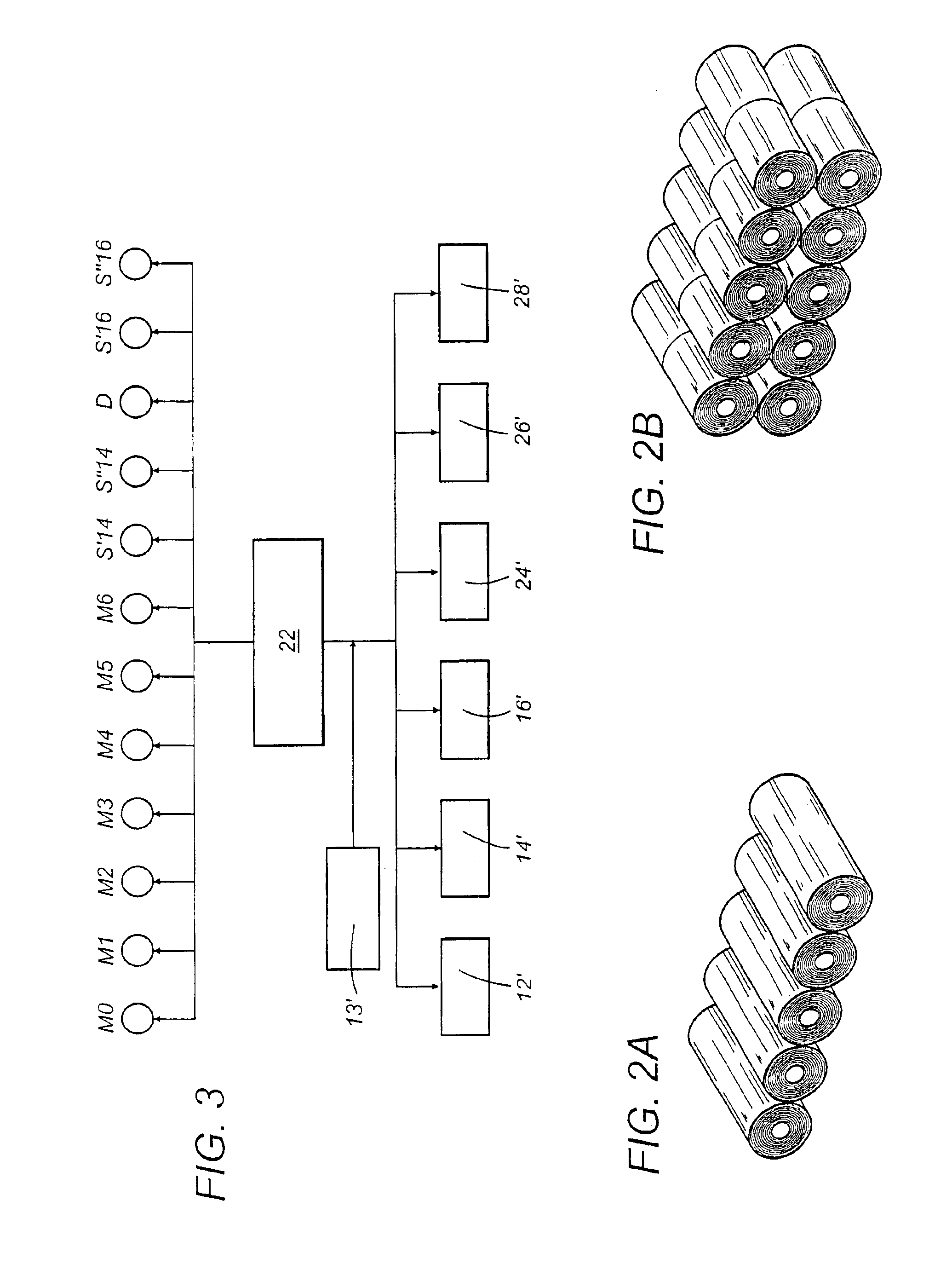
[0067]As FIG. 2A shows, the pack could, for instance, be constituted by a longitudinal row of rolls and by a single layer thereof, or, as shown in FIG. 2B, said pack could, for instance, be constituted by two layers of rolls, each of which is in turn subdivided into two respective parallel rows of said rolls. Obviously, with respect to what is shown in FIGS. 2A and 2B, the pack of rolls to be ...

second embodiment

[0148]FIG. 8 shows plant, in particular for obtaining articles in the form of paper rolls or the like.

[0149]This second embodiment presents a roll forming machine which, in known fashion, comprises, schematically, a series of sections that provide the logs to be cut into rolls, starting from a main loading coil, of considerable size, obtained directly from the paper mill. Said sections comprise an initial coil loading section 2, which generally supports at least a first and a second of said loading coils to allow for a continuous feeding of the apparatus for producing rolls and which unwinds the paper strip from the feeding coil and for transferring it to a successive section 4 for embossing the paper strip. Downstream of the embossing section, a re-coiling section 3, which receives the core tubes from an appropriate section 5 for their forming, winds on these elongated tubes a quantity of paper having a diameter corresponding to that of the rolls to be produced, obtaining the logs ...


PUM

PropertyMeasurementUnit
lengthaaaaaaaaaa
lengthaaaaaaaaaa
conveying velocityaaaaaaaaaa

Abstract

A method for defining the operation of a plant for producing, conveying and packaging articles. The articles include rolls, such as rolls of paper material and the like. The plant includes the following operative sections: at least an apparatus for forming articles positioned upstream, at least a machine for packaging the articles in respective packs positioned downstream, and an apparatus for conveying the articles which is able to transfer the articles between the forming apparatus and the packaging apparatus. The method and the plant provide that, through a central control unit of the plant, starting from predefined setting data, operating parameters of the sections of the plant are determined.

Description

CROSS REFERENCE TO RELATED APPLICATIONS[0001]This application is a division of application Ser. No. 09 / 791,781, filed on Feb. 26, 2001, now U.S. Pat. No. 6,715,265, the entire contents of which are hereby incorporated by reference.FIELD OF THE INVENTION[0002]The present invention relates to a method of operation of a plant for producing, conveying and packaging articles, in particular articles in the form of rolls.[0003]The present invention also relates to a plant for producing, conveying and packaging said articles, and to an apparatus usable in said plant.BACKGROUND OF THE INVENTION[0004]In particular, the present invention relates to a plant for producing, conveying and packaging rolls of strip-like material wound on a support core, for instance in the form of rolls of paper material or the like destined to domestic or similar use, wound on a cardboard core tube. Such rolls are preferably rolls of toilet paper, kitchen paper, aluminum foil and other materials destined to persona...

Claims


Application Information

Patent Timeline
Patent Type & Authority Patents(United States)
IPC IPC(8): B65B35/44B65B25/14B65B57/00B65B57/16
CPCB65B25/146B65B35/44B65B57/00B65B57/16B65B65/003G05B19/41865B65B59/00G05B2219/31386G05B2219/31385B65B65/006B65B2210/02Y02P90/02
Inventor FRANZAROLI, MASSIMO
Owner PULSAR SRL
Why Eureka
Try Eureka