
Communications control method and information relaying device for communications network system

a communication network and information relaying technology, applied in the direction of data switching networks, instruments, unauthorized memory use protection, etc., can solve problems such as wasteful and troublesome work, communication failures,

Inactive Publication Date: 2008-04-15
ALAXALA NETWORKS
View PDF11 Cites 65 Cited by
  • Summary
  • Abstract
  • Description
  • Claims
  • Application Information

AI Technical Summary

Benefits of technology

[0008]It is an object of the present invention to provide a management technology and an information relaying technology of a communications network system which make it possible to prevent the communication failure caused by erroneously setting a logical or physical network address and to speed up the analysis of the cause of the communication failure and the recovery from the communication failure.
[0009]It is another object of the present invention to provide a management technology and an information relaying technology of a communications network system which make it possible to improve security of the communications network system by preventing tapping data or feigning another person by a malignant user.
[0013]As a first respect, the present invention provides a management method of the LAN switch network system which enables to prevent communication failure caused by erroneously setting an IP address or the like and tapping data or feigning another person by a malignant user in a communications network system composed of LAN switches and is characterized by the following points in the communications network system such as an IP subnet-based VLAN or the like:
[0018]The management method of the LAN switch network system viewed from the first respect makes it possible to automatically restart the similar communication to that before the movement if each PC is moved from one port to another port of the LAN switch. In this movement, the pre-registered user name and password are prompted by the LAN switch. Hence, no user other than the user having known the password can tap the information or pass itself off as another user. Moreover, a user of a PC may erroneously set the IP address of another PC to his or her PC and connects to the port of the LAN switch. In this case, the message reporting the erroneous setting (including the user name of the PC having the erroneously set IP address) is sent to the user of another PC and the administrator of the LAN switch. Hence, the user of another PC and the administrator of the LAN switch can easily classify (analyze) the cause of the failure. This makes it possible to do a swift recovering process.
[0027]The LAN switch arranged according to the third respect enables to reduce the traffic load of repeating a request for entering a user name and a password burdened when the IP address or the like is erroneously set or a malignant user taps the data or passes himself or herself off as another person by using the address of another PC.
[0031]Further, the foregoing LAN switch is arranged to eliminate mails to be sent to a true user at a successful rewriting time (if a true user does communications in a proper range of use) for reducing a traffic amount and to report the result only if the rewrite is failed for more rapidly classifying (analyzing) the cause of the failure and recovering the communication from the failure.

Problems solved by technology

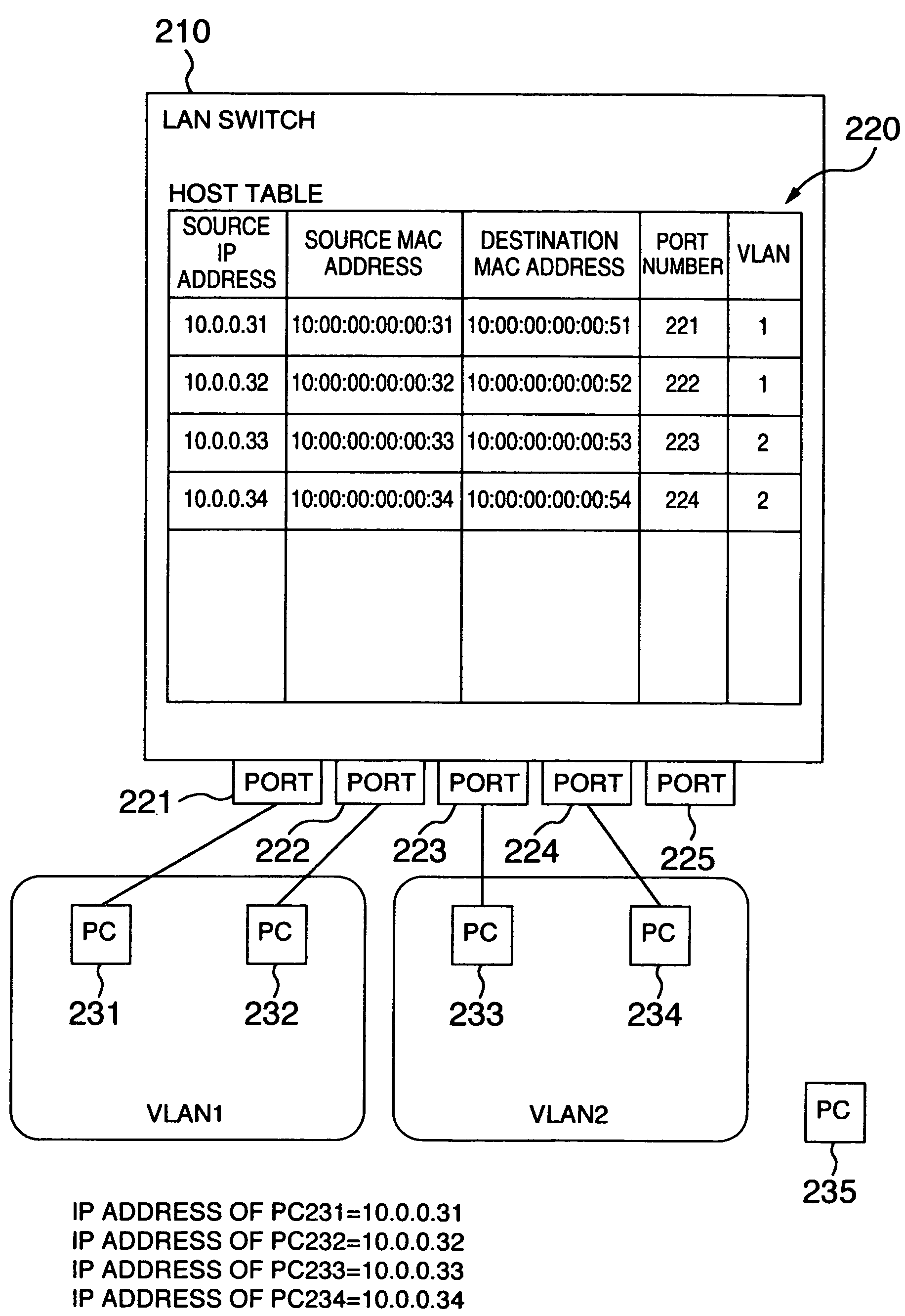
First, the prior art has no guard against the erroneous setting of an IP address or the like. For example, it is assumed that a user of the PC 232 erroneously sets an IP address of the PC 231 to the PC 232 and connects the PC 232 to the port 222. In this assumption, the LAN switch 210 determines that the PC 231 is moved from the port 221 to the port 222 and rewrites the host table 220 based on the determination. As a result, some communication failure may take place. For example, the PC 231 with the correct IP address set thereto disables to do any communication. If lots of PCs are connected to the network, it is necessary to do a wasteful and troublesome work to analyze the cause of the communication failure and recover the communication from the failure.
Second, the prior art allows a malignant user to tap the data or pass himself or herself off as another person. For example, it is assumed that a user of the PC 235 erroneously sets the IP address of the PC 231 to the PC 235 and connects the PC 235 to the port 255. In this assumption, the LAN switch 210 determines that the PC 231 is moved from the port 221 to the port 225 and rewrites the host table 220 based on the determination. As a result, the user of the PC 235 receives the data destined for the PC 231 and taps it or passes himself or herself off as the user of the PC 231.

Method used


Image

  • Communications control method and information relaying device for communications network system
  • Communications control method and information relaying device for communications network system
  • Communications control method and information relaying device for communications network system

Examples


Embodiment Construction

[0044]Hereafter, the embodiments of the invention will be described with reference to the appended drawings.

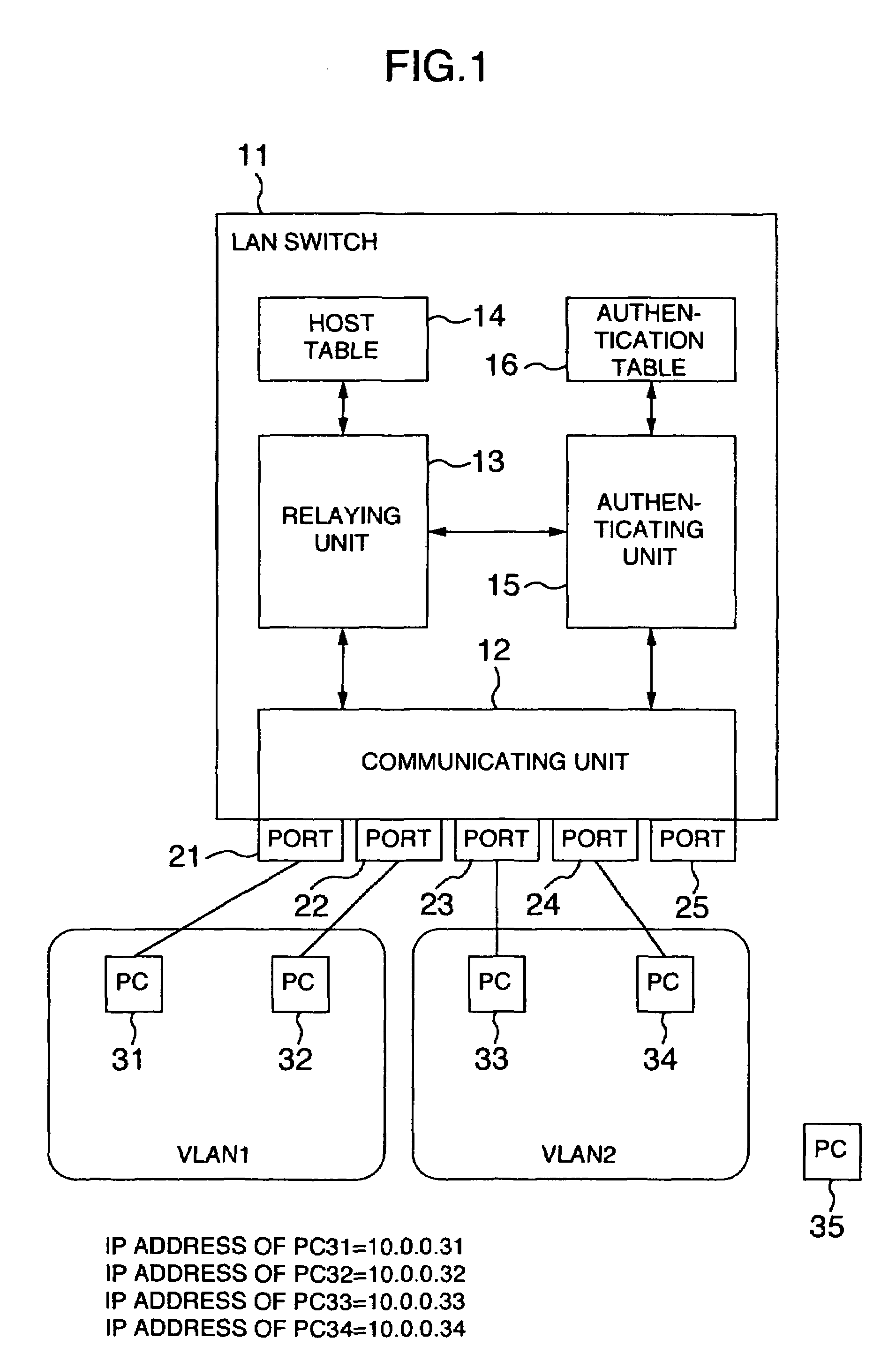
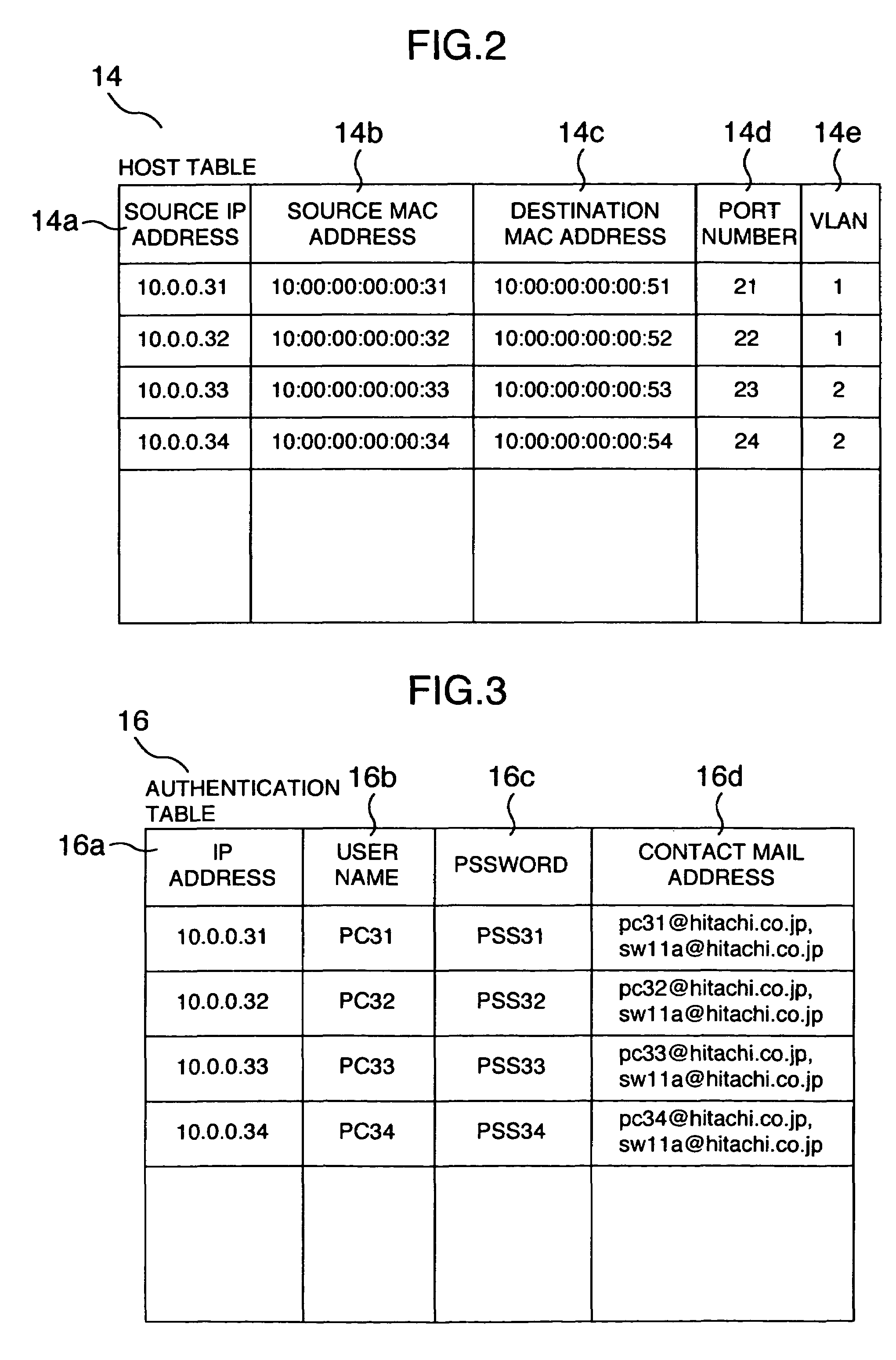
[0045]FIG. 1 is a conceptual view showing an arrangement of a LAN switch for implementing a management method of a communications network system according to a first embodiment of the invention and an IP subnet based VLAN to which the LAN switch is applied. FIGS. 2 and 3 are conceptual views showing various kinds of control informations used in the LAN switch according to this embodiment. FIGS. 4 to 6 are flowcharts showing the management method of the communications network system and the function of the LAN switch according to this embodiment.

[0046]The LAN switch 11 of this embodiment is arranged to relay packets among ports 21 to 25 based on a host table 14 as shown in FIG. 2 created by learning the connection information from the received packets (communication information), for realizing the communication among the PCs 31 to 34. The LAN switch 11 is composed of a communic...


PUM


Abstract

A LAN switch is one component of a communications network system composed of a virtual LAN having network terminals such as personal computers connected with ports respectively. The LAN switch provides a host table for holding correspondence between each port and address information of the network terminal connected to each port and an authentication table for holding information for authenticating a user of each network terminal. If a request takes place of changing the correspondence about the source network terminal held in the host table when relaying the packets, the LAN switch prompts a user name and a password for the source network terminal, does user authentication on the basis of the information held in an authentication table, and enables rewrite of the host table and relay of the packets if the user is correct. These processes are executed for easily preventing false use of an address or tapping or false access by a malignant user as well as analyzing or recovering the erroneously set address.

Description

BACKGROUND OF THE INVENTION[0001]The present invention relates to a communications control technology and an information relaying technology intended for a communications network system such as a LAN (Local Area Network). More particularly, the present invention relates to the technology which may be effectively applied to a communication control method intended for an inter-network device such as a LAN switch (Layer 2 switch, Layer 3 switch, or the like) and a communications network system composed of the inter-network devices.[0002]One of the technologies characterized by the LAN switch is a VLAN (Virtual LAN). The VLAN is a technology which makes it possible to build the LAN without depending upon a physical port of the inter-network device. The VLAN may be divided into the following types; a port-based VLAN, a MAC (Media Access Control) address-based VLAN, a Layer 3 protocol-based VLAN, an IP (Internet Protocol) subnet-based VLAN, and the like.[0003]For example, in the communica...

Claims


Application Information

Patent Timeline
Patent Type & Authority Patents(United States)
IPC IPC(8): H04L9/00H04L12/28H04L12/56H04L9/32H04L12/44H04L12/46H04L12/66H04L45/50H04L69/40H04W12/06H04W40/34
CPCH04L12/44H04L12/4625H04L12/4641H04L63/083
Inventor TSUCHIYA, KAZUAKINOZAKI, SHINJI
Owner ALAXALA NETWORKS
Learn More