
Display device

a technology of a display device and a display plate, which is applied in the direction of display means, illuminated signs, instruments, etc., can solve the problems of degrading the luminance, difficulty in forming switching elements and interconnects having sizes of certain levels or less under the constraints of their electric performance capabilities and fabrication techniques, and further reducing the aperture ratio

Inactive Publication Date: 2010-04-08
SHARP KK
View PDF7 Cites 14 Cited by
  • Summary
  • Abstract
  • Description
  • Claims
  • Application Information

AI Technical Summary

Benefits of technology

[0030]According to the present invention, the distribution of the luminance of a display device provided with a high-directivity edge-light type backlight and light condensing elements can be made uniform.

Problems solved by technology

With a transistor provided for each pixel, the area of each pixel decreases, causing a problem of degrading the luminance.
Moreover, it is difficult to form switching elements and interconnects having sizes of certain levels or less under the constraints of their electric performance capabilities and fabrication techniques.
Hence, as the pitch of pixels becomes smaller with achievement of higher definition and a smaller size in liquid crystal display devices, the aperture ratio further decreases, and this makes the problem of degrading the luminance noticeable.
Such a transflective liquid crystal display device has a problem that since the reflection region must be wide to some extent, the area ratio of the transmission region to one pixel decreases, and this degrades the luminance in the transmission mode.
However, in medium to small sized liquid crystal display devices, particularly in liquid crystal display devices mounted in mobile equipment, in which an edge-light type backlight is used for thinning and weight-saving, it is difficult to obtain light with high parallelism.
However, while the directivity of light emerging from the edge-light type backlights described in these documents is higher than that conventionally attained, it fails to be as high as the directivity (half-width: ±2°, for example) obtained by a light source used in a projection type liquid crystal display device, for example.
Also, the backlights disclosed in the above documents have a problem that the directivity of light emerging from the backlight varies with the azimuth (azimuth in the liquid crystal panel plane).

Method used


Image

  • Display device
  • Display device
  • Display device

Examples


Embodiment Construction

[0056]A display device of an embodiment of the present invention will be described with reference to the relevant drawings. Hereinafter, the liquid crystal display device of an embodiment of the present invention will be described taking as an example a transflective liquid crystal display device provided with transmission regions adapted to display in the transmission mode and reflection regions adapted to display in the reflection mode. It should however be noted that the present invention is not limited to this but can be widely applied to display devices capable of conducting display in at least the transmission mode.

[0057][Liquid Crystal Display Device]

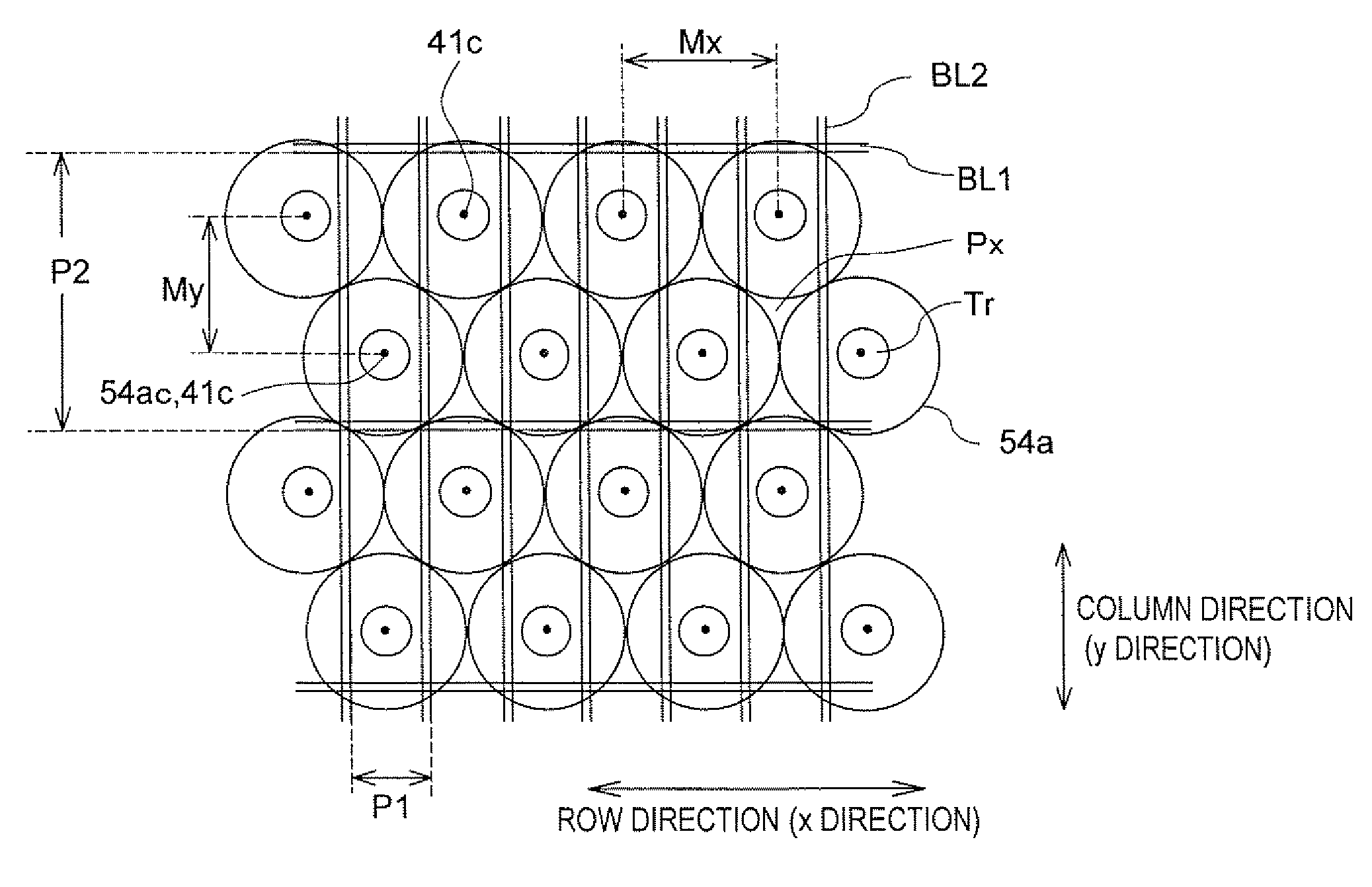
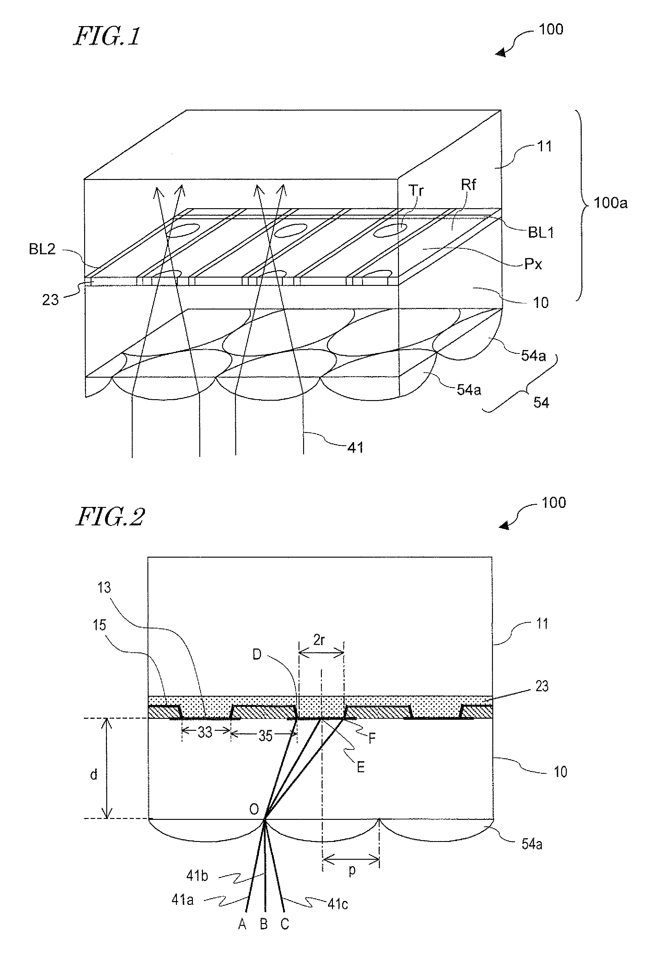
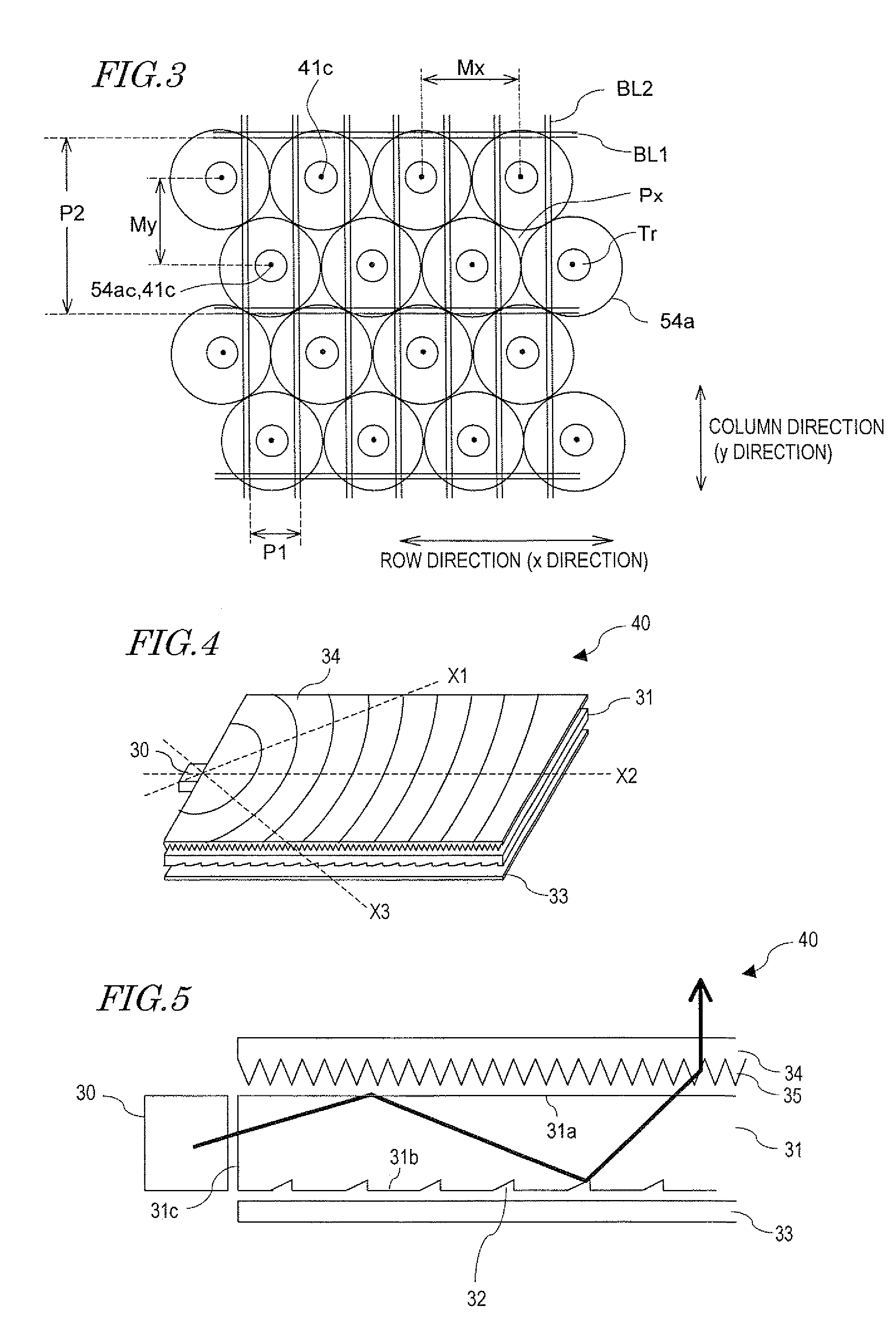
[0058]FIG. 1 is a perspective view diagrammatically showing a transflective liquid crystal display device 100 of this embodiment. As shown in FIG. 3, the transflective liquid crystal display device 100 includes a lighting device (not shown), a display panel 100a having a plurality of pixels Px arranged in a matrix and a light con...


PUM

PropertyMeasurementUnit
polar angleaaaaaaaaaa
azimuth angleaaaaaaaaaa

Abstract

A display device of the present invention includes: a display panel 100a including a plurality of pixels arranged in a matrix; a lighting device 50 including a light source 30 and a light guide plate 31 for outputting light toward the front; and a plurality of light condensing elements 54a placed between the display panel and the lighting device. The directivity of light emerging from the lighting device to be incident on the light condensing elements varies with the position in the display panel plane, and when the range of a polar angle of light, out of the light emerging from the lighting device to be incident on the light condensing elements, that is used for display after passing through the light condensing elements and then the display panel, with respect to the normal to the display panel plane determined based on geometrical optics is ±ω or less and the luminous flux within the range of the polar angle ±ω (within ∠AOC) is Φω, the minimum one of values of luminous flux Φω at the centers of nine regions, obtained by dividing a region corresponding to the display region of the display panel plane into nine equal parts, is 70% or more of the maximum one of the values.

Description

TECHNICAL FIELD[0001]The present invention relates to a display device and more particularly to a non-luminous display device that uses light from a lighting device for display.BACKGROUND ART[0002]Types of non-luminous display devices include liquid crystal display devices, electrochromic display devices, electrophoretic display devices and the like. Among others, liquid crystal display devices are in widespread use in personal computers, cellular phones and the like, for example.[0003]Liquid crystal display devices are configured to display images, letters and the like by changing the optical properties of a liquid crystal layer at its pixel openings with a drive voltage applied to each of pixel electrodes arranged regularly in a matrix. In such liquid crystal display devices, for individual control of a plurality of pixels, thin film transistors (TFTs), for example, are provided as switching elements for such pixels. Interconnects are also provided for supply of predetermined sign...

Claims


Application Information

Patent Timeline
Patent Type & Authority Applications(United States)
IPC IPC(8): G02F1/1335G02F1/13357
CPCG02B6/0053G02F1/133555G02F1/133526G02B6/0061
Inventor WATANABE, HISASHISATO, TAKASHI
Owner SHARP KK
Learn More