
Convertible charge-pump circuit

Active Publication Date: 2010-04-08
HIMAX TECH LTD
View PDF4 Cites 29 Cited by
  • Summary
  • Abstract
  • Description
  • Claims
  • Application Information

AI Technical Summary

Problems solved by technology

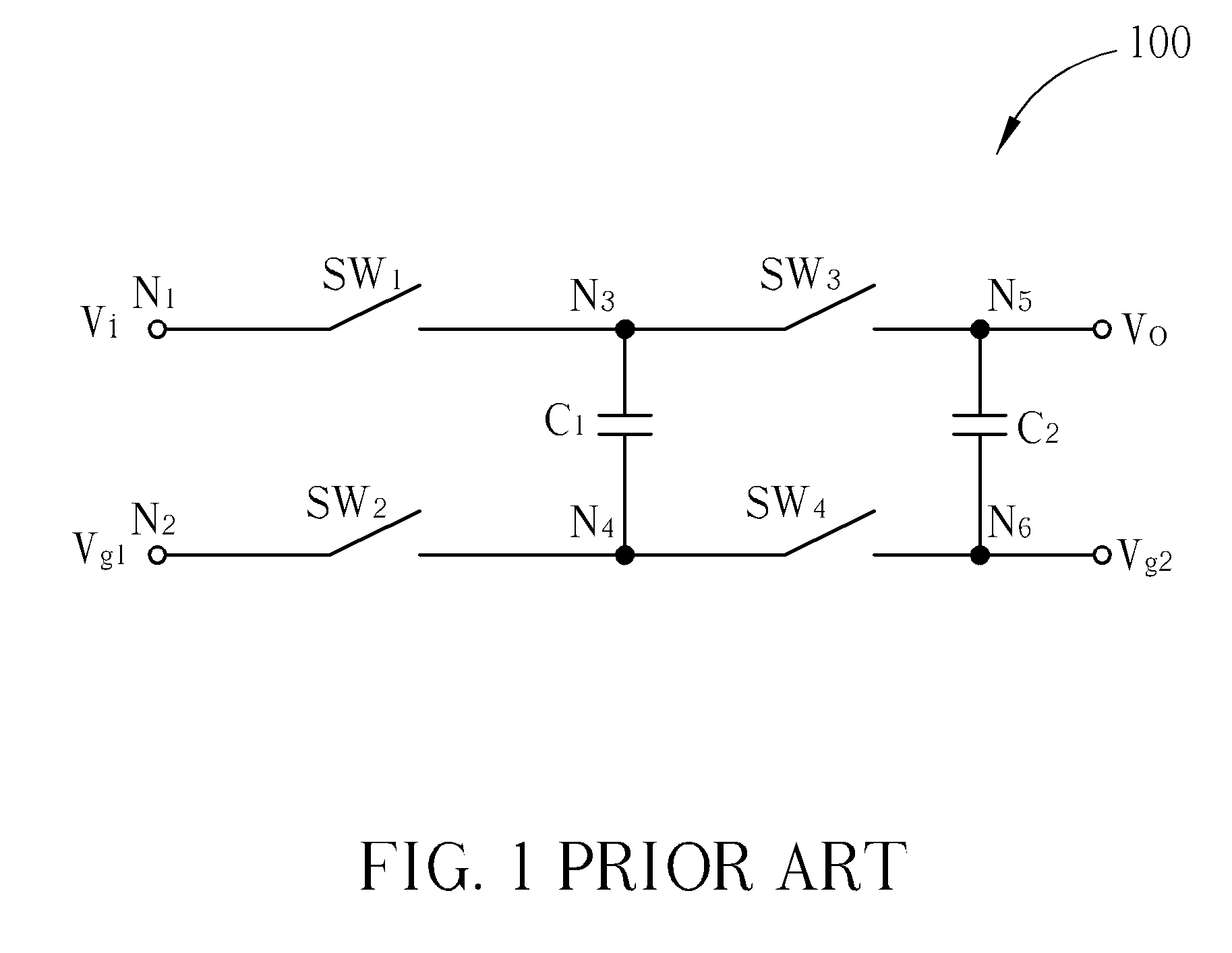
The charging capacitor C1 and the pumping capacitor C2 in the charge-pump circuit occupy a large area and significantly increase the cost of the charge-pump circuit.
Therefore, lowering the occupied area and cost of each charge-pump circuit is an urgent problem in this field.

Method used


Image

  • Convertible charge-pump circuit
  • Convertible charge-pump circuit
  • Convertible charge-pump circuit

Examples


Embodiment Construction

[0017]Certain terms are used throughout the description and following claims to refer to particular components. As one skilled in the art will appreciate, electronic equipment manufacturers may refer to a component by different names. This document does not intend to distinguish between components that differ in name but not function. In the following description and in the claims, the terms “include” and “comprise” are used in an open-ended fashion, and thus should be interpreted to mean “include, but not limited to . . . ”. Also, the term “couple” is intended to mean either an indirect or direct electrical connection. Accordingly, if one device is coupled to another device, that connection may be through a direct electrical connection, or through an indirect electrical connection via other devices and connections.

[0018]Different features of the present invention are detailed as below in reference to the figures, and for convenience of explanation, the same elements in separate fig...


PUM


Abstract

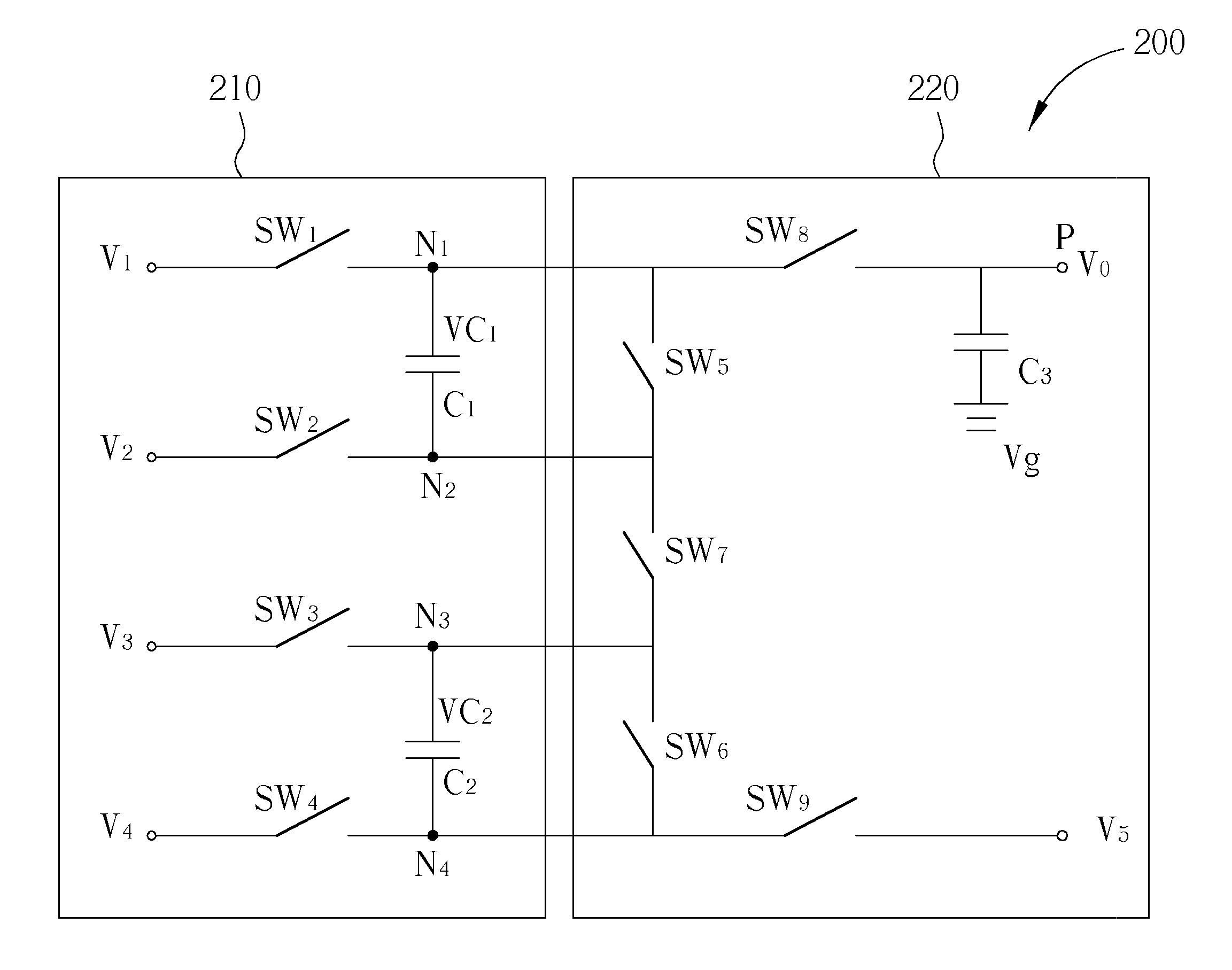
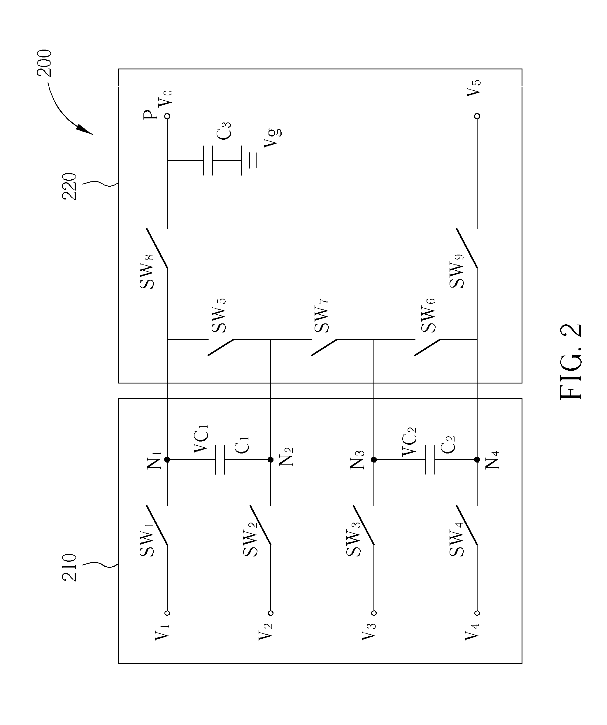
A convertible charge-pump circuit includes: a charging circuit having a plurality of charging capacitors and a pumping circuit having an output port coupled to a pumping capacitor. The charging circuit is configured for charging the charging capacitors to store a plurality of potential differences, respectively, when the convertible charge-pump circuit is in a charging phase. The pumping circuit is configured for selecting at least one charging capacitor from the charging capacitors charged in the charging phase to generate an output voltage level at the output port according to a potential difference stored in the selected charging capacitor when the convertible charge-pump circuit is in a pumping phase.

Description

BACKGROUND OF THE INVENTION[0001]1. Field of the Invention[0002]The present invention relates to a charge-pump circuit, and more particularly, to a charge-pump circuit having a convertible discharging path.[0003]2. Description of the Prior Art[0004]A charge-pump circuit is utilized for generating a required output voltage, and is one of the most important elements in a displaying apparatus. Please refer to FIG. 1. FIG. 1 is a diagram illustrating a conventional charge-pump circuit 100. The charge-pump circuit 100 includes a first input switch SW1, a second input switch SW2, a first output switch SW3, a second output switch SW4, a charging capacitor C1, and a pumping capacitor C2. A node N1 of the first input switch SW1 receives the input voltage Vi, and a node N2 of the second input switch SW2 is coupled to a first ground reference voltage Vg1. The charging capacitor C1 is coupled between nodes N3 and N4, and the pumping capacitor C2 is coupled between nodes N5 and N6, in which the ...

Claims


Application Information

Patent Timeline
IPC IPC(8): H02M3/18
CPCH02M3/07
Inventor CHIU, MING-CHENGHSU, CHIN-FENG
Owner HIMAX TECH LTD
Learn More