Video encoding and decoding method and apparatus

Inactive Publication Date: 2010-04-08
KK TOSHIBA
View PDF15 Cites 95 Cited by
  • Summary
  • Abstract
  • Description
  • Claims
  • Application Information

AI Technical Summary

Benefits of technology

[0006]An object of the present invention is to enable optimization of a quantization process using localit

Problems solved by technology

However, according to the technique suggested in JP-A 2006-262004, it is only possible to switch whether or not to use the quantization matrix, and optimization of a quantization process that conside

Method used


Image

  • Video encoding and decoding method and apparatus
  • Video encoding and decoding method and apparatus
  • Video encoding and decoding method and apparatus

Examples


Example

First Embodiment

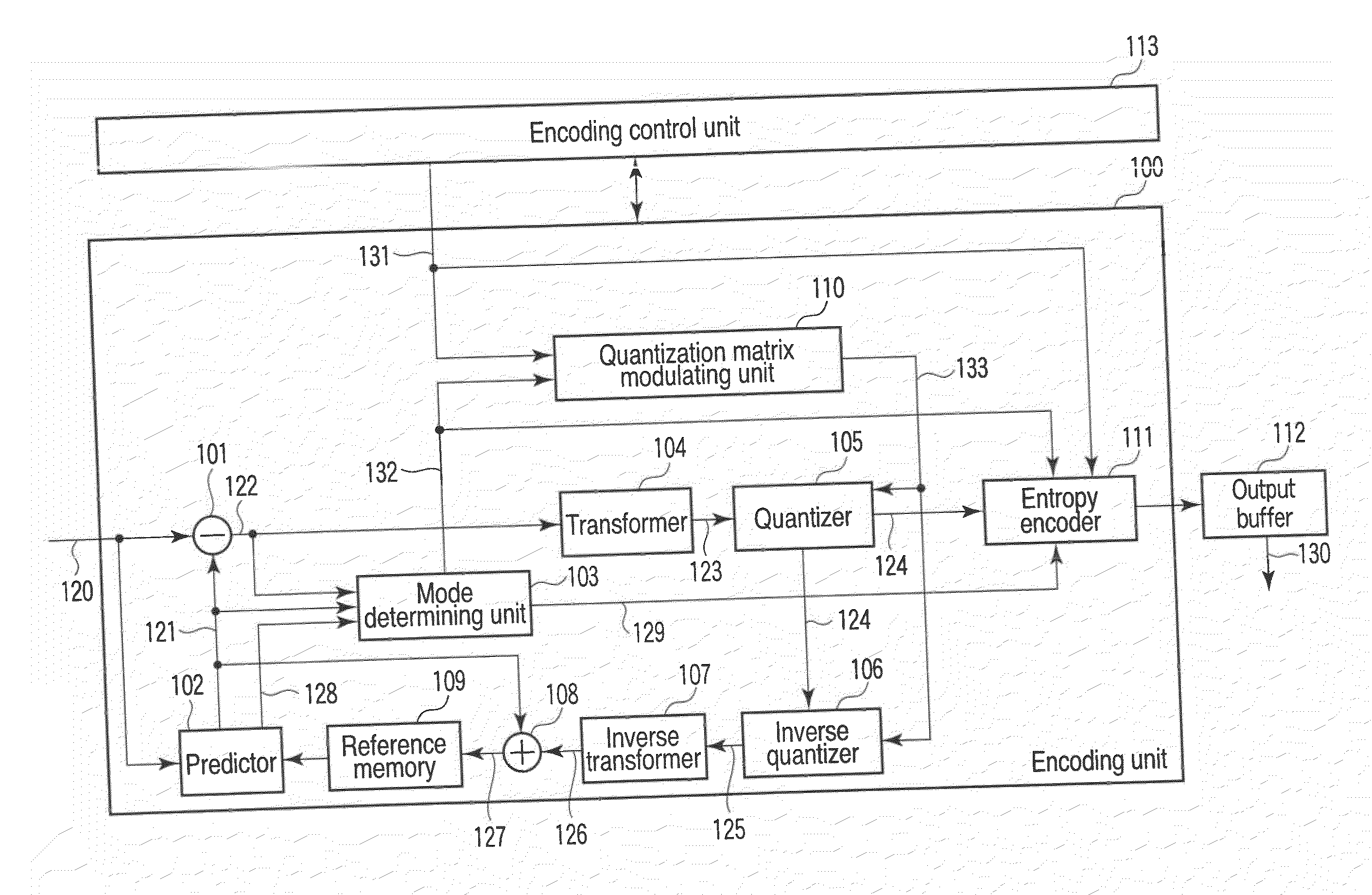
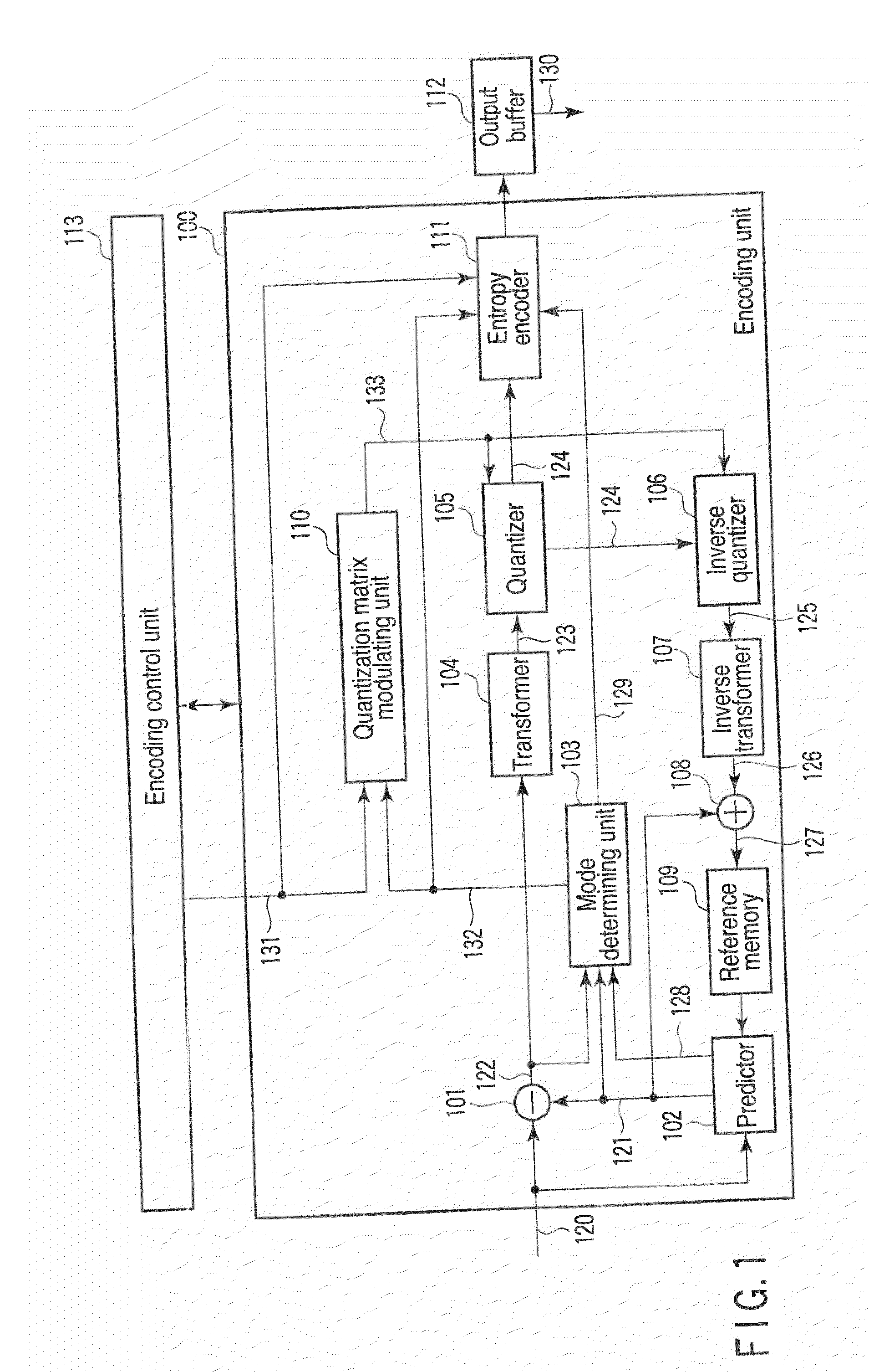
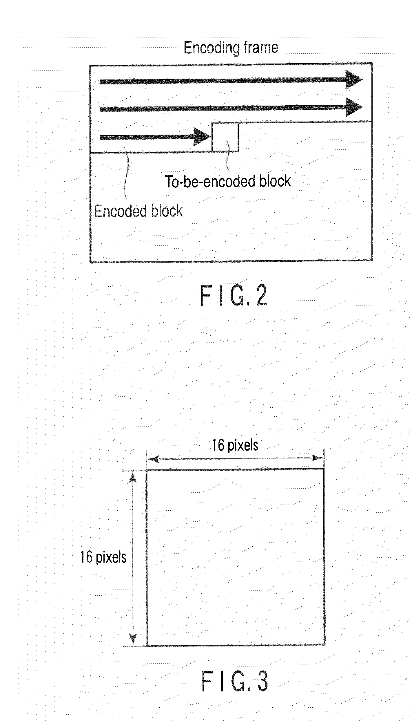
[0050]Referring to FIG. 1, in a video encoding apparatus according to the first embodiment of the present invention, an input image signal 120 of a motion video or a still video is divided in units of a small pixel block, for example, in units of a macroblock, and is input to an encoding unit 100. In this case, a macroblock becomes a basic process block size of an encoding process. Hereinafter, a to-be-encoded macroblock of the input image signal 120 is simply referred to as a target block.

[0051]In the encoding unit 100, a plurality of prediction modes in which block sizes or methods of generating a prediction image signal are different from each other are prepared. As the methods of generating the prediction image signal, an intra-frame prediction for generating a prediction image in only a to-be-encoded frame and an inter-frame prediction for performing a prediction using a plurality of temporally different reference frames are generally used. In this embodiment, f...

Example

Second Embodiment

[0156]When the quantizer 105 and the inverse quantizer 106 perform quantization and inverse quantization corresponding to the equations 6 and 18, instead of performing the modulation on the quantization matrix as in the first embodiment, a modulation may be performed on an operation precision control parameter to control operation precision at the time of quantization / inverse quantization. In this case, the equations 6 and 18 are changed as follows.

Y(i,j)=sign(X(i,j))×(abs(X(i,j))×QM(i,j)×MLS(i,j,idx)+f)Qbit(26)X′(i,j)=sign(Y(i,j))×(abs(Y(i,j))×QM(i,j)×IMLS(i,j,idx))Qbit(27)

[0157]Here, MLS and IMLS are modulated operation precision control parameters, which are expressed by the following Equation.

MLS(i,j,idx)=(LS(i,j)+MM(i,j,idx))   (28)

IMLS(i,j,idx)=(ILS(i,j)+MM(i,j,idx))   (29)

[0158]As such, the modulation on the operation precision control parameters LS and ILS is almost equal to the modulation on the quantization matrix by adjusting a value of the modulation mat...

Example

Third Embodiment

[0163]When the quantizer 105 and the inverse quantizer 106 perform quantization and inverse quantization corresponding to the equations 4 and 16, instead of performing the modulation on the quantization matrix as in the first embodiment, a modulation may be performed on the quantization parameter. In this case, Equations 4 and 16 are transformed as follows.

Y(i,j)=sign(X(i,j))×(abs(X(i,j))×QM(i,j)×LS(i,j)+f)(QPstep(i,j,idx))(30)X′(i,j)=sign(Y(i,j))×(abs(Y(i,j))×QM(i,j)×ILS(i,j)×(QPstep(i,j,idx))(31)

[0164]Here, QPstep is a modulation quantization parameter, which is represented by the following equation.

QPstep(i,j,idx)=(Qstep+MM(i,j,idx))   (32)

[0165]Here, Qstep denotes a quantization parameter.

[0166]As such, the modulation on the quantization parameter Qstep is synonymous to the modulation on the quantization matrix. With respect to the quantization / inverse quantization as in the equations 5 and 17 and the equations 6 and 18, a modulation can be performed on the quant...


PUM


Abstract

A video encoding apparatus includes a predictor to perform prediction for an input image signal to generate a prediction image signal, a subtractor to calculate a difference between the input image signal and the prediction image signal to generate a prediction residual signal, a transformer to transform the prediction residual signal to generate a transform coefficient, a modulating unit to perform modulation on a quantization matrix to obtain a modulated quantization matrix, a quantizer to quantize the transform coefficient using the modulated quantization matrix to generate a quantized transform coefficient, and an encoder to encode the quantized transform coefficient and a modulation index to generate encoded data.

Description

TECHNICAL FIELD[0001]The present invention relates to a video encoding and decoding method and apparatus for a motion video or a still video.BACKGROUND ART[0002]In recent years, a video encoding method in which encoding efficiency is greatly improved has been recommended as ITU-T Rec. H.264 and ISO / IEC 14496-10 (hereinafter, referred to as H.264) in conjunction with ITU-T and ISO / IEC. Encoding methods, such as ISO / IEC MPEG-1, 2 and 4, and ITU-T H.261 and H.263, perform compression using a two-dimensional DCT of 8×8 blocks. Meanwhile, since a two-dimensional integer orthogonal transform of 4×4 blocks is used in the H.264, an IDCT mismatch does not need to be considered, and an operation using a 16-bit register is enabled.[0003]Further, in an H.264 high profile, a quantization matrix is introduced for a quantization process of orthogonal transform coefficients, as one tool for subjective image quality improvement for a high-definition image like an HDTV size (refer to J. Lu, “Proposal...

Claims


Application Information

Patent Timeline
IPC IPC(8): H04N7/50
CPCH04N19/176H04N19/147H04N19/61H04N19/126H04N19/18H04N19/192H04N19/70H04N19/157H04N19/19H04N19/124H04N19/51
Inventor TANIZAWA, AKIYUKICHUJOH, TAKESHI
Owner KK TOSHIBA
Why Eureka
Try Eureka