Vehicle door handle assembly

Inactive Publication Date: 2010-04-15
MAGNA MIRRORS OF AMERICA INC
View PDF102 Cites 51 Cited by
  • Summary
  • Abstract
  • Description
  • Claims
  • Application Information

AI Technical Summary

Benefits of technology

[0007]The low profile characteristic of the bracket and counterweight allows the door handle assembly to be implemented in narrower or reduced profile doors, where the bracket and counterweight may be disposed in a narrow space between the outer door panel and the movable glass window of the door assembly when the glass window is at least partially lowered into the door cavity. For example, the bracket and counterweight may have a profile or lateral dimension (when mounted to a vehicle door) that is about one and three quarters of an inch or less, depending on the particular application of the door handle assembly and vehicle door.
[0008]Optionally, the door handle assembly of the present invention may utilize a bell crank that can be staged for easy of product assembly into a vehicle. The staged bell crank and bracket may cooperate to allow for loading of the handle portion or strap handle without interference, and may allow for unstaging of the bell crank (to move the bell crank to its operational position) via pulling at the handle portion or strap handle after assembly of the door handle at the vehicle door.
[0009]The counterweight is interconnected with the handle portion such that pivotal movement of the handle portion to open the vehicle door imparts a pivotal movement of the counterweight. Thus, the counterweight is pivoted or cycled each time the door is opened via pivotal movement of the handle portion. Such cycling limits or substantially precludes any accumulation of dirt, dust or other contaminants at the counterweight that may restrict pivotal movement of the counterweight during a sudden stop or collision of the vehicle.

Problems solved by technology

Due to the weight or mass of the pivotable handle portion, the handle portion tends to swing or pivot outward during a vehicle collision and may open the door of the vehicle during the collision.

Method used


Image

  • Vehicle door handle assembly
  • Vehicle door handle assembly
  • Vehicle door handle assembly

Examples


Embodiment Construction

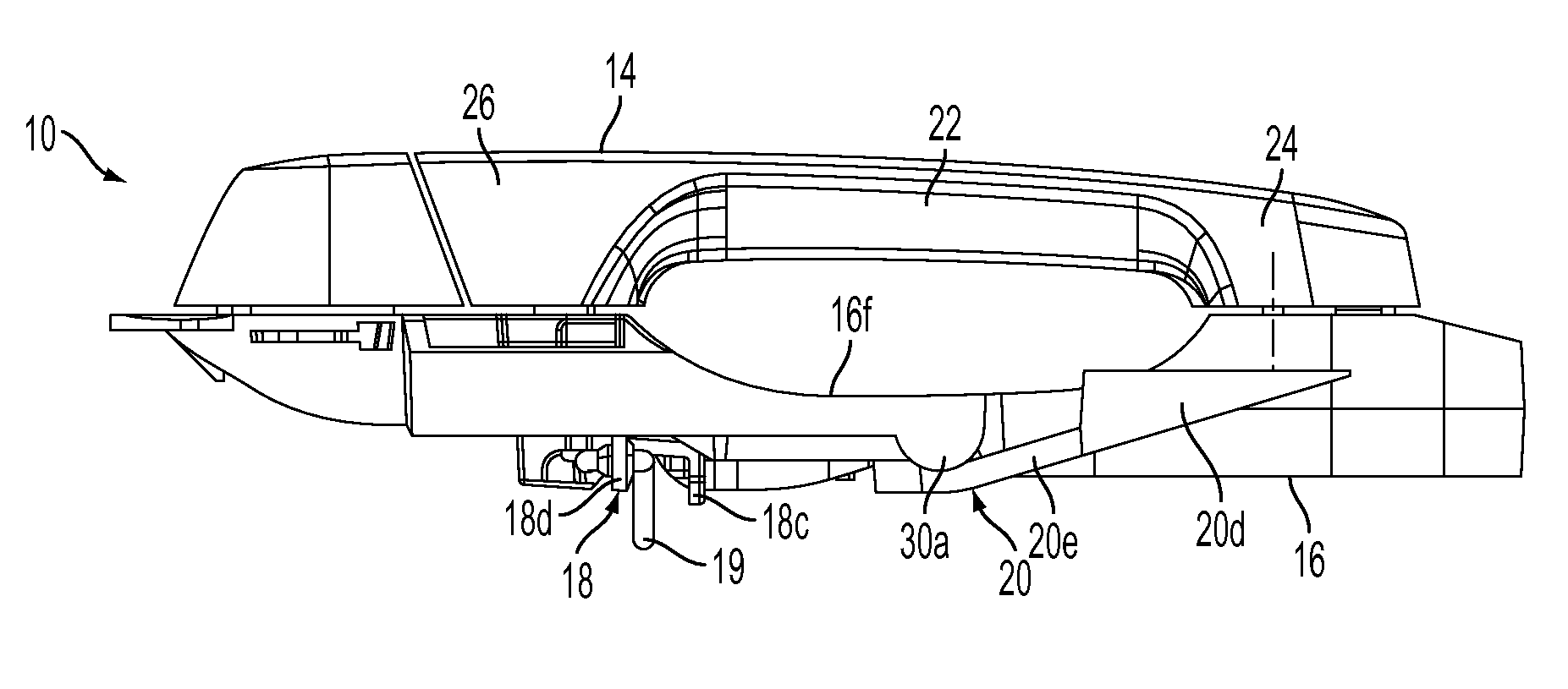
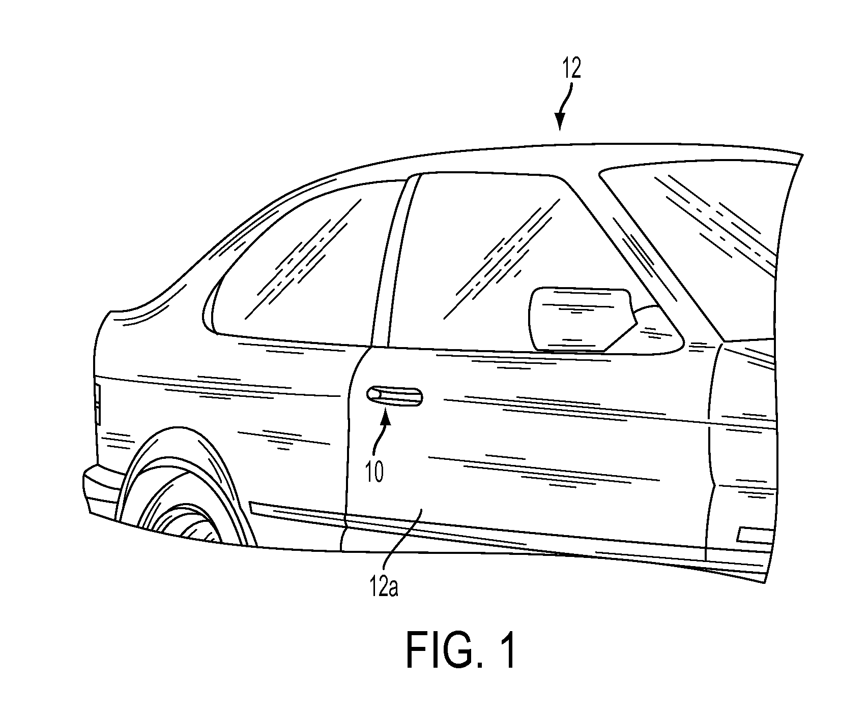
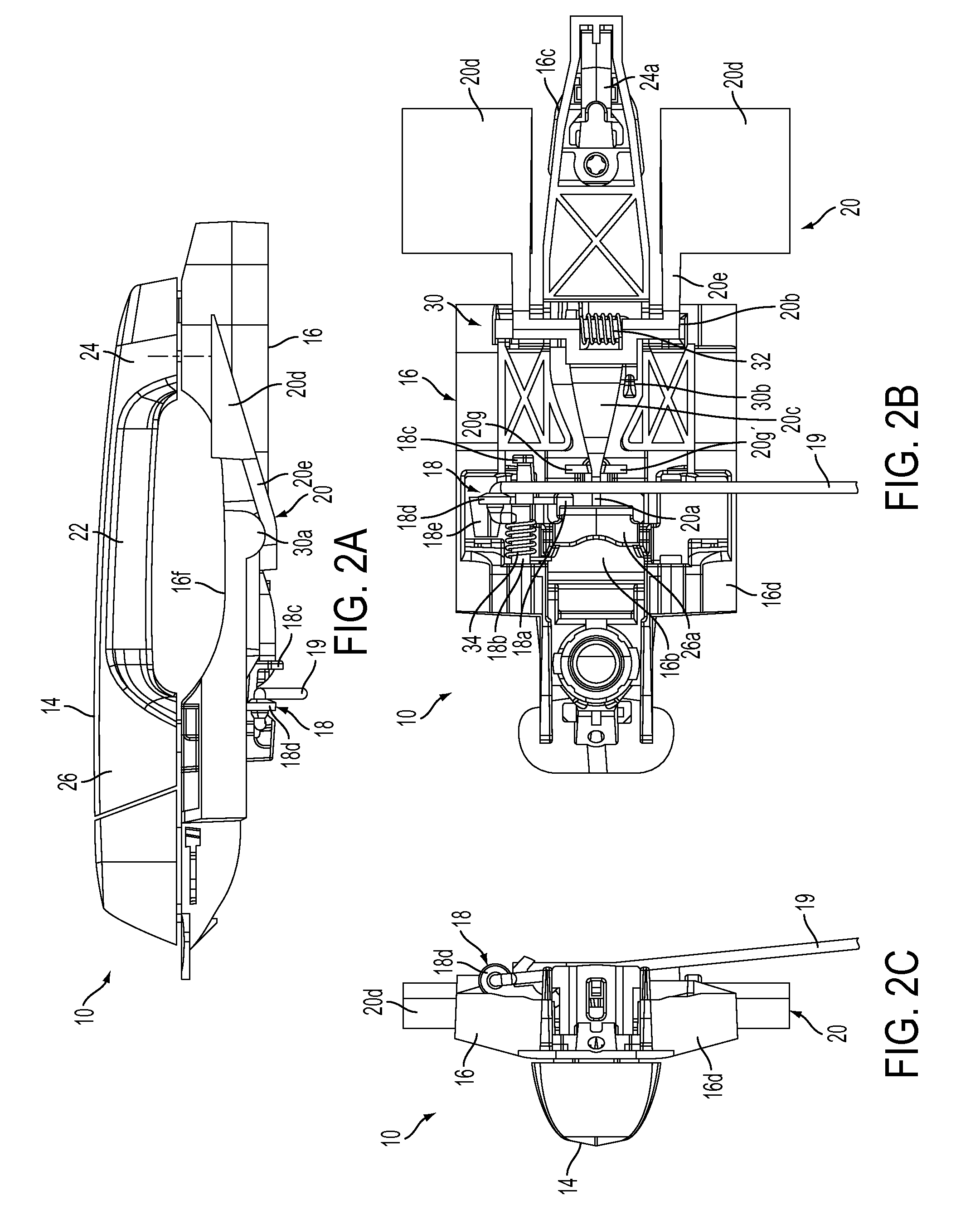
[0061]Referring now to the drawings and the illustrative embodiments depicted therein, a vehicle door handle assembly 10 is mountable to a door 12a of a vehicle 12 and operable to release a latch mechanism (not shown) of the door 12a to open the vehicle door (FIG. 1). Handle assembly 10 includes a handle portion 14 that is mountable to a base portion or bracket 16, which in turn is mounted to the vehicle door and within the vehicle door, an actuating lever or member or element or arm or bellcrank 18 pivotally mounted to bracket 16 and a counterweight or counterbalance 20 pivotally mounted to bracket 16 (FIGS. 2A-C and 3A-C). Actuating element 18 is connected to the door latch mechanism, such as via a cable or mechanical linkage or the like 19, such that pivotal movement by handle portion 14 imparts a pivotal movement of actuating element 18 to release the latch mechanism to open the vehicle door, as discussed below. Likewise, pivotal movement by handle portion 14 imparts a pivotal m...


PUM


Abstract

A door handle assembly for a vehicle includes a bracket mountable to the vehicle door, a handle portion configured to pivotally attach to the bracket and an actuating element pivotally mounted to the bracket. The actuating element connects to a release mechanism of the vehicle door so as to actuate the release mechanism when the actuating element is pivoted relative to the bracket. The door handle assembly may include a counterweight pivotally mounted to the bracket, with the counterweight extending along the bracket, such that the counterweight and the bracket comprise a low profile assembly. The door handle assembly may include an inertial catch pivotally mounted to the bracket, wherein pivotal movement of the handle portion imparts a pivotal movement of the inertial catch during normal operation of the door handle assembly to open the vehicle door.

Description

CROSS REFERENCE TO RELATED APPLICATIONS[0001]The present application claims benefit of U.S. provisional applications, Ser. No. 61 / 161,792, filed Mar. 20, 2009; and Ser. No. 61 / 105,108, filed Oct. 14, 2008, which are hereby incorporated herein by reference in their entireties.FIELD OF THE INVENTION[0002]The present invention relates to door handles for vehicles and, more particularly, to an exterior door handle for opening a side door of a vehicle.BACKGROUND OF THE INVENTION[0003]Typically, a door handle for a vehicle may include, a handle portion that is pivotable relative to a base portion, whereby pivotal movement of the handle portion pulls at a cable to move a latch mechanism to release the latch and open the door. Due to the weight or mass of the pivotable handle portion, the handle portion tends to swing or pivot outward during a vehicle collision and may open the door of the vehicle during the collision. The door handle thus often includes a counterweight and lever mechanism ...

Claims


Application Information

Patent Timeline
Patent Type & Authority Applications(United States)
IPC IPC(8): B25G3/00E05B1/00B25G1/00
CPCE05B77/06Y10T16/458E05B85/16
Inventor RUSE, JAMES A.GORBY, BRETT A.
Owner MAGNA MIRRORS OF AMERICA INC
Why Eureka
Try Eureka